Rhino Pi X1R
Product Overview
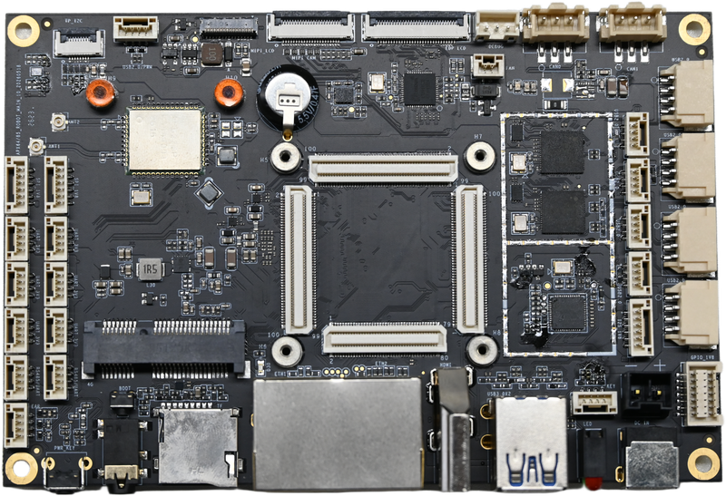
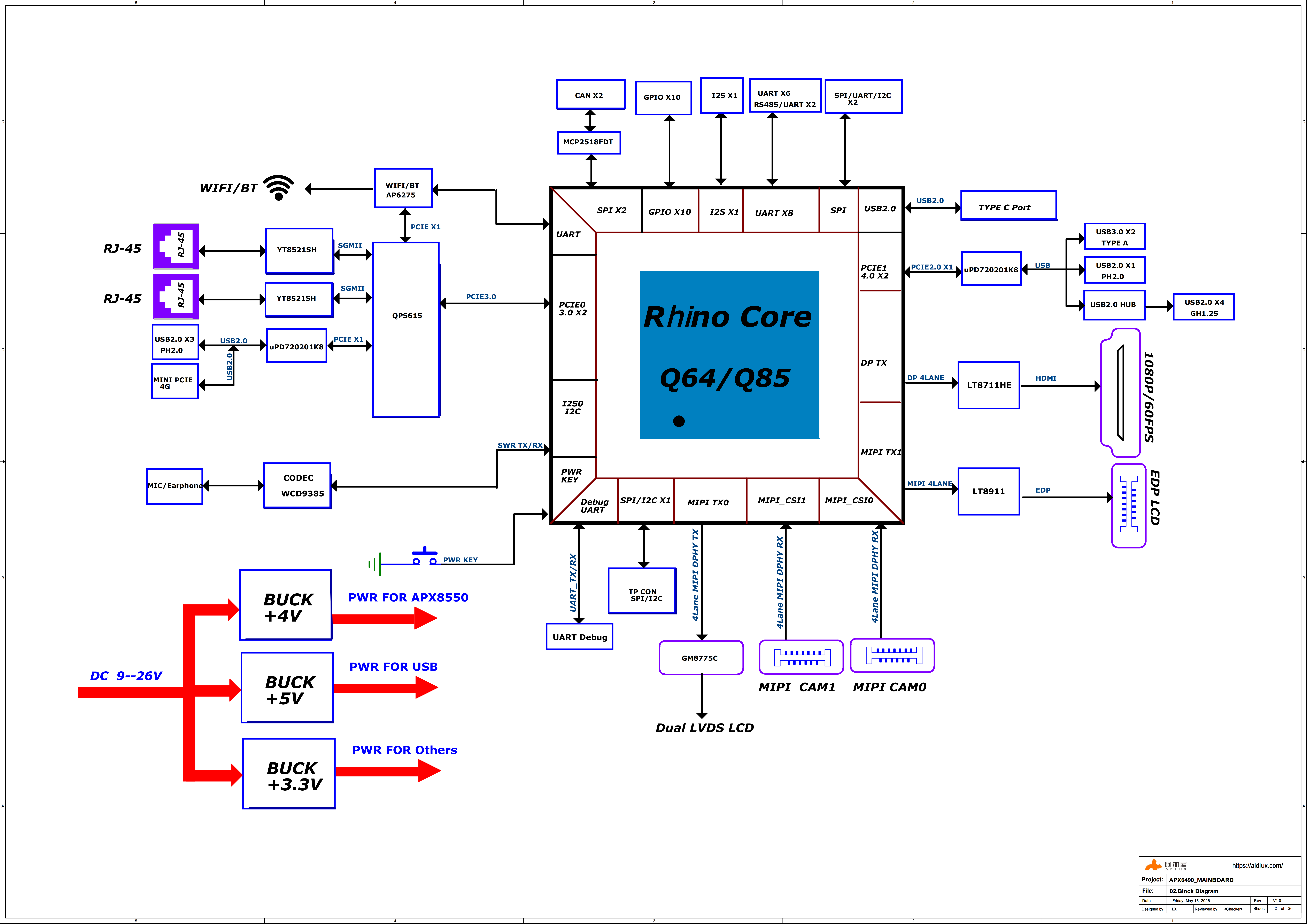
The Rhino Pi X1R mainboard is compatible with both the Rhino Core Q85 and Rhino Core Q64 smart modules. The mainboard provides a rich set of data communication interfaces, supporting dual Gigabit RJ45 Ethernet, USB 3.0 Type-A and expansion USB 2.0 connectors, as well as display interfaces such as MIPI DSI/CSI, HDMI, and eDP. It also supports multiple general-purpose bus interfaces including SPI, I2C, RS485, UART, I2S, CAN, and GPIO. An onboard WiFi 6 + BT 5.3 module, a standard Mini-PCIe interface for 4G communication expansion, an external Micro SD card slot for storage expansion, and audio input/output interfaces are also provided. The board is designed for high-compute and high-stability scenarios such as robotics, industrial AI, and high-end IPC/VR applications.
This mainboard is developed with strictly selected materials and careful design. Its compact size and rich interfaces make it easy to integrate into complete products. Paired with different core boards, it can meet the performance requirements of various product configurations, and can be applied in industries such as digital signage, touch interaction, consumer electronics, and entertainment systems.
Operating System
Ubuntu 22.04 (native Linux version) is provided by default, targeting edge AI, robotics, and embedded development.
Rhino Core Q85 Smart Module
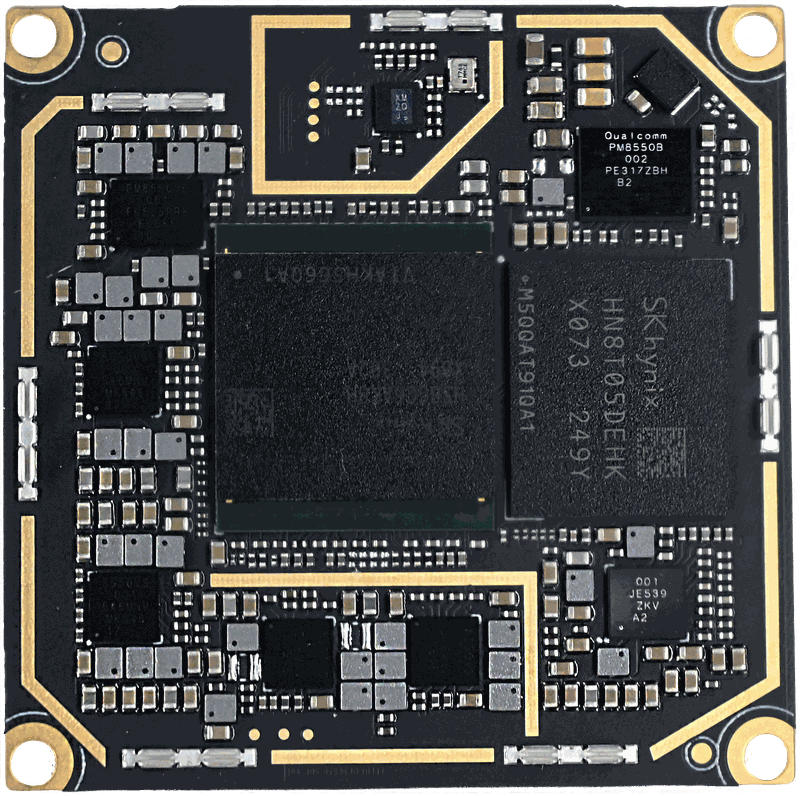
Front
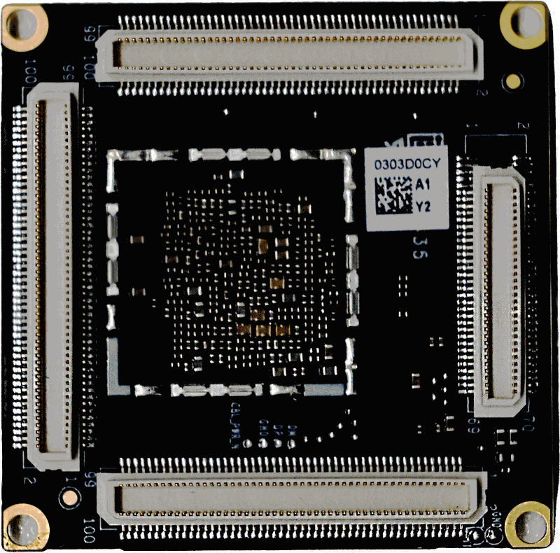
Back
Mainboard Shared by Rhino Pi X1R and A1R
System Block Diagram
Product Specifications
| Category | Specification |
|---|---|
| Core Board | Rhino Core Q85 smart module |
| TF Card | Push-push TF card socket, supports up to 256GB TF card |
| USB | 2 Type-A (USB 3.0 ×2), 4 built-in 1.25mm latching vertical connectors (USB 2.0 ×4), 4 2.0mm latching horizontal connectors (USB 2.0 ×4) |
| HDMI | Standard HDMI display interface, supports 4K@60Hz output |
| LCD Interface | Industry-standard 30-pin eDP socket; 4-lane MIPI DSI display interface |
| Touch | FPC interface, supports I2C touch |
| Camera | 2× MIPI CSI × 4-lane |
| I2S Interface | 1× I2S interface |
| Ethernet | 2× 10/100/1000M auto-negotiation Ethernet RJ45 ports |
| Mini-PCIe | Industry-standard m-PCIe 4G module interface |
| SIM Card | Push-push Nano SIM card socket, supports mobile communication |
| CAN Bus | 2× CAN pin header interfaces, supports CAN 2.0B and CAN FD |
| Codec | Low-power voice processing and audiophile-grade audio playback (supports 4 microphones) |
| Headphone/Microphone | Supports US-standard 4-pole 3.5mm headset combo jack (left-right-ground-mic) |
| SPI Bus | 2 individual SPI pin header interfaces, 1 shared with I2C |
| GPIO | Supports 10 external 1.8V GPIOs |
| Serial Communication | Supports RS485/UART communication, 2× RS485, 6× UART |
| Buttons | Flashing button (RECOVERY) and power button |
| Power Input | Supports 10~24V wide-voltage DC input (12V/3A recommended) |
| Debug Interface | Supports external 3.3V serial debug |
| Line Output | Supports standard left/right channel line output (pin header interface + headphone interface) |
| WiFi / Bluetooth | Onboard WiFi 6 + BT 5.3 |
| Environmental Requirements | Operating temperature -25°C ~ 50°C, storage temperature -40°C ~ 85°C, operating humidity 0%~95% (non-condensing) |
| Physical Dimensions | L × W × H (135mm × 90mm × 14mm), PCB front height 9mm |
| Operating System | Ubuntu 22.04 |
Quick Access
 Quick Start
Quickly understand the platform features and getting-started steps
 System Usage
System usage instructions such as network configuration
 Carrier Board Hardware & Interfaces
Onboard resources, interface definitions, and peripheral connection development
 Application Development
Source code, kernel, driver, and AI application development
 Resource Download
Images, tools, and design resources download
Related Module DocumentationSpecifications, pinouts, power, and carrier board design
FAQ & TroubleshootingCommon questions and solutions