Board Hardware
Interfaces
I/O Electrical Characteristics
The smart camera device uses optocoupler-isolated input/output. The optocoupler input current is 5~50 mA, with a typical value of 20 mA (recommended input current of 20 mA for optimal optocoupler input performance). The optocoupler output voltage should not exceed 80 V. The figure below shows the test circuit for optocoupler response time.
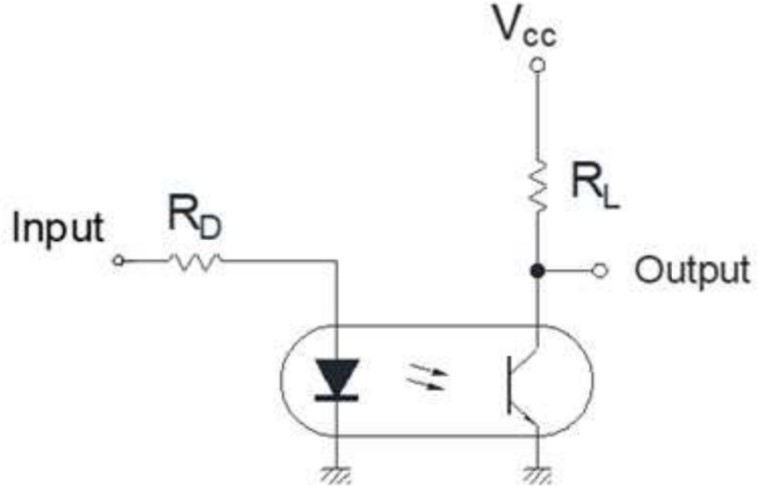
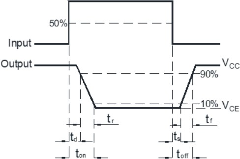
Test environment: VCC=5V, IC=2mA, RL=100Ω
Response Time (Rise): tr typical 4 µs, maximum 18 µs
Response Time (Fall): tr typical 3 µs, maximum 18 µs
I/O Circuit
Two-Channel Optocoupler Output Circuit
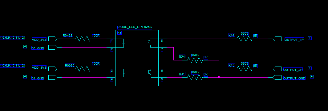
Device D1 is an optocoupler. The optocoupler input is connected to the smart camera main controller, and the output is connected to external devices via the smart camera 20-pin connector (i.e., the smart camera controls external devices through optocoupler isolation). On the smart camera side, the OUTPUT_1P and OUTPUT_2P signal currents are controlled at 20 mA. OUTPUT_1P and OUTPUT_2P are the two output signals, and OUTPUT_GND is the common ground for the two output signals.
Two-Channel Optocoupler Input Circuit
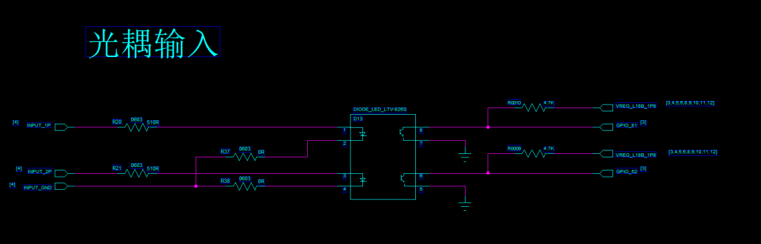
Device D13 is an optocoupler. The optocoupler input is connected to external devices via the smart camera 20-pin connector, and the optocoupler output is connected to the smart camera main controller (i.e., external devices control the smart camera through optocoupler isolation). INPUT_1P and INPUT_2P are the two input signals, and INPUT_GND is the common ground for the two input signals.
Note: Since the optocoupler input voltage is determined by the external device, to meet the optimal input current of 20 mA, the external device can configure the resistor values on the INPUT_1P and INPUT_2P input signals. Currently, the smart camera is configured with a 510 ohm resistor by default. The input voltage range is 5~20 V, with a recommended input voltage of 10 V. For special voltage input requirements, please configure the resistors on the external device accordingly.
External I/O Wiring Methods
Optocoupler Output Signal
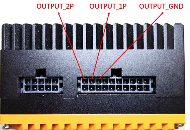
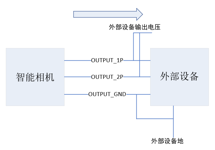
OUTPUT_1P and OUTPUT_2P are the two output signals, and OUTPUT_GND is the common ground for the two output signals. The output voltage of the external device must not exceed 80 V.
Optocoupler Input Signal
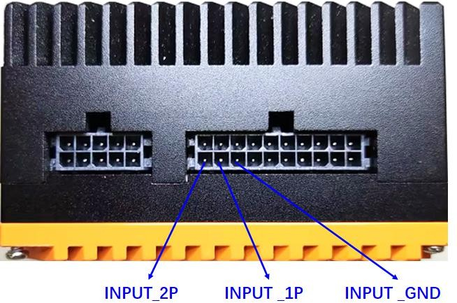
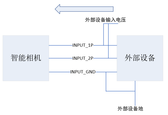
INPUT_1P and INPUT_2P are the two input signals, and INPUT_GND is the common ground for the two input signals. External input voltage range: 5~20 V, recommended 10 V. If changes to the input voltage range are required, resistors can be connected in series on the INPUT_1P and INPUT_2P signals on the external device based on specific needs.
Buttons
- Power Button: Long press 15 s to reboot
Indicators
- LED Indicator (Network Port): Network port status indication
- LED Indicator (System): System status indication
Power
- Power Interface: DC 12V IN
Structure Dimensions
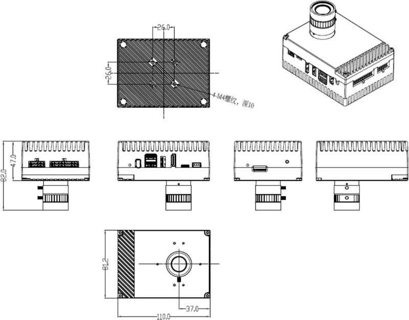
The maximum external dimensions of the device are L × W × H = 110 × 81.2 × 82 mm. There are two sets of mounting holes on the side and back, equipped with M4 threaded holes, with a hole spacing of 26 × 26 mm.
Device Design Suggestions
Mounting and Fixation
TBD.
Heat Dissipation
TBD.
Peripheral Expansion
TBD.
Power Adapter
TBD.