USB to Serial Device
USB TO 4CH TTL
- Official kit documentation: USB TO 4CH TTL
Preparation
- Rhino Pi-A1
- USB TO 4CH TTL serial device
- CH340 USB TO TTL test board
- Several jumper wires
- Windows computer
Hardware Connection
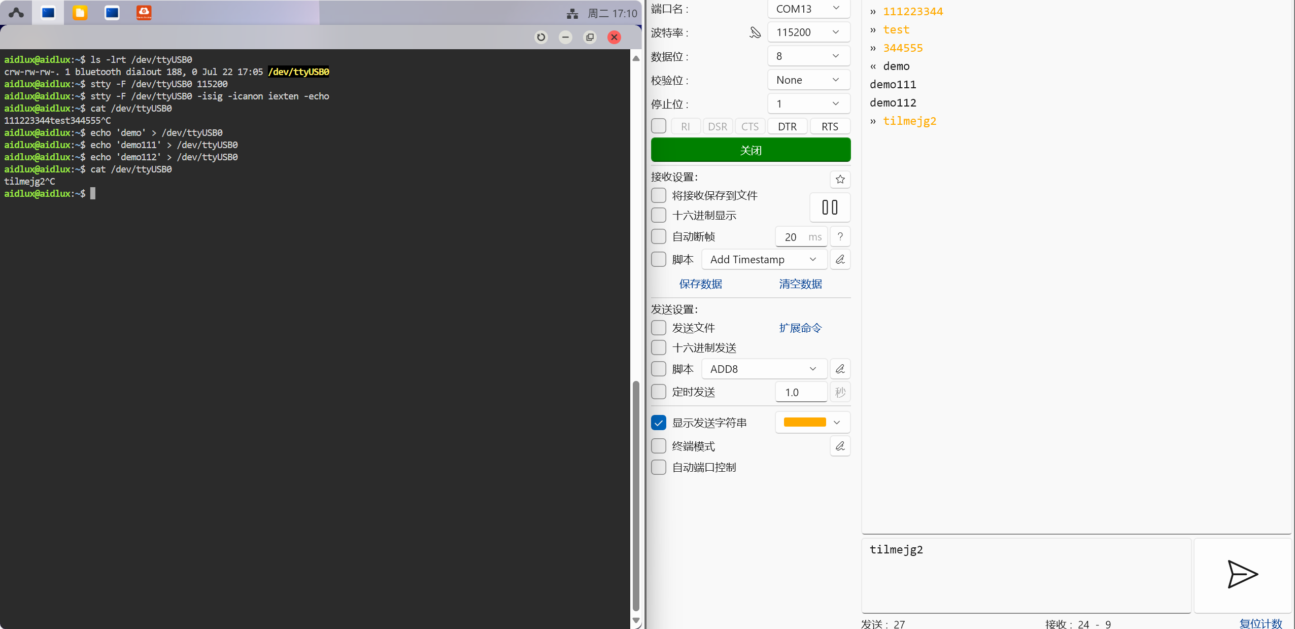
- Connect the development board to the CH344 device via a USB interface
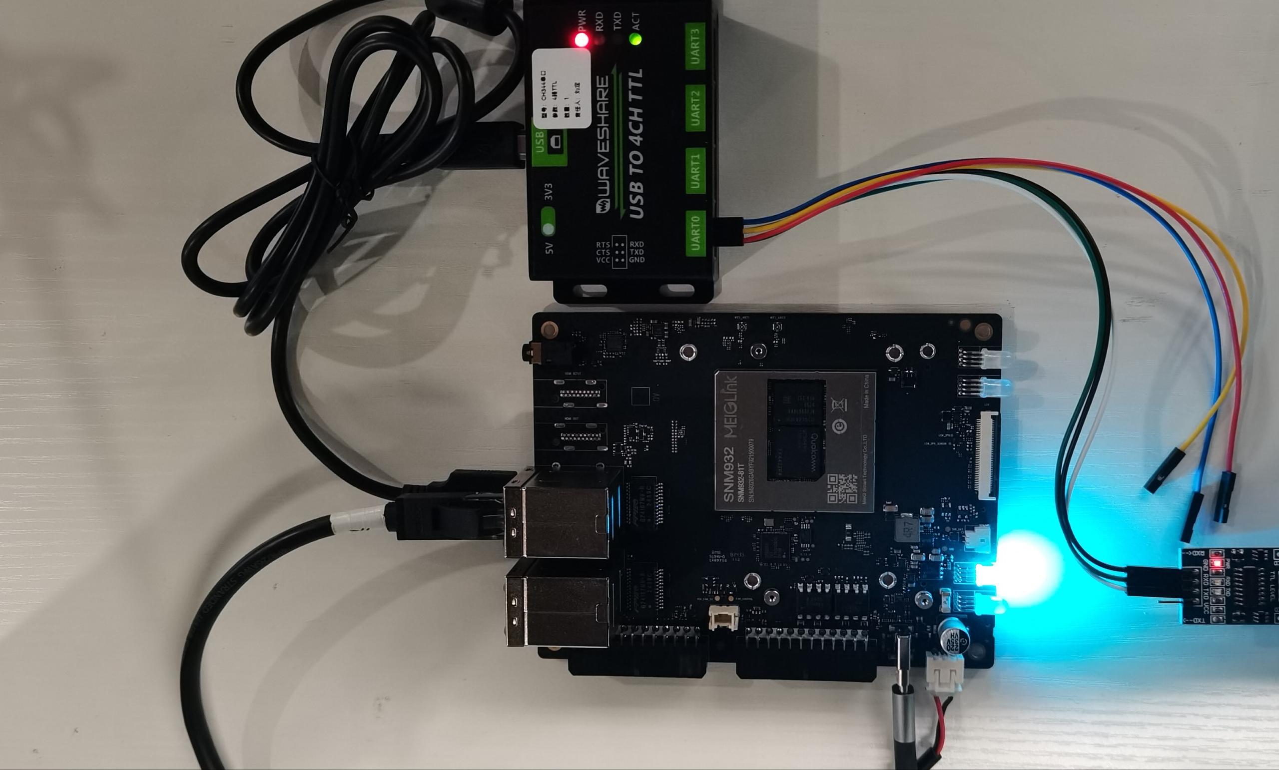
- Connect the CH340 test board to the Windows computer USB port and the CH344 device
Where: the RXD, TXD, and GND of the CH344 connect to the TXD, RXD, and GND of the CH340
Testing
Note
When executing commands in the terminal on the AidLux desktop, if the aidlux password is required, enter: aidlux
After obtaining the IP address of the Rhino Pi-A1, log in to the AidLux Web desktop via the browser. For the specific login method, please refer to Web Login.
After logging in, enter the following command in the AidLux terminal to check whether the CH344 serial device has been recognized.
ls -l /dev/ttyC*
Note
The multi-channel serial device names of the CH344 correspond one-to-one to the actual physical UART interface names, i.e., /dev/ttyCH343USB0 corresponds to UART0; /dev/ttyCH343USB1 corresponds to UART1, and so on.
- Use the stty tool in the AidLux terminal to configure the device UART ports.
stty -F /dev/ttyCH343USB0 115200   # Set ttyCH343USB0 baud rate to 115200
stty -F /dev/ttyCH343USB0 -isig -icanon iexten -echo
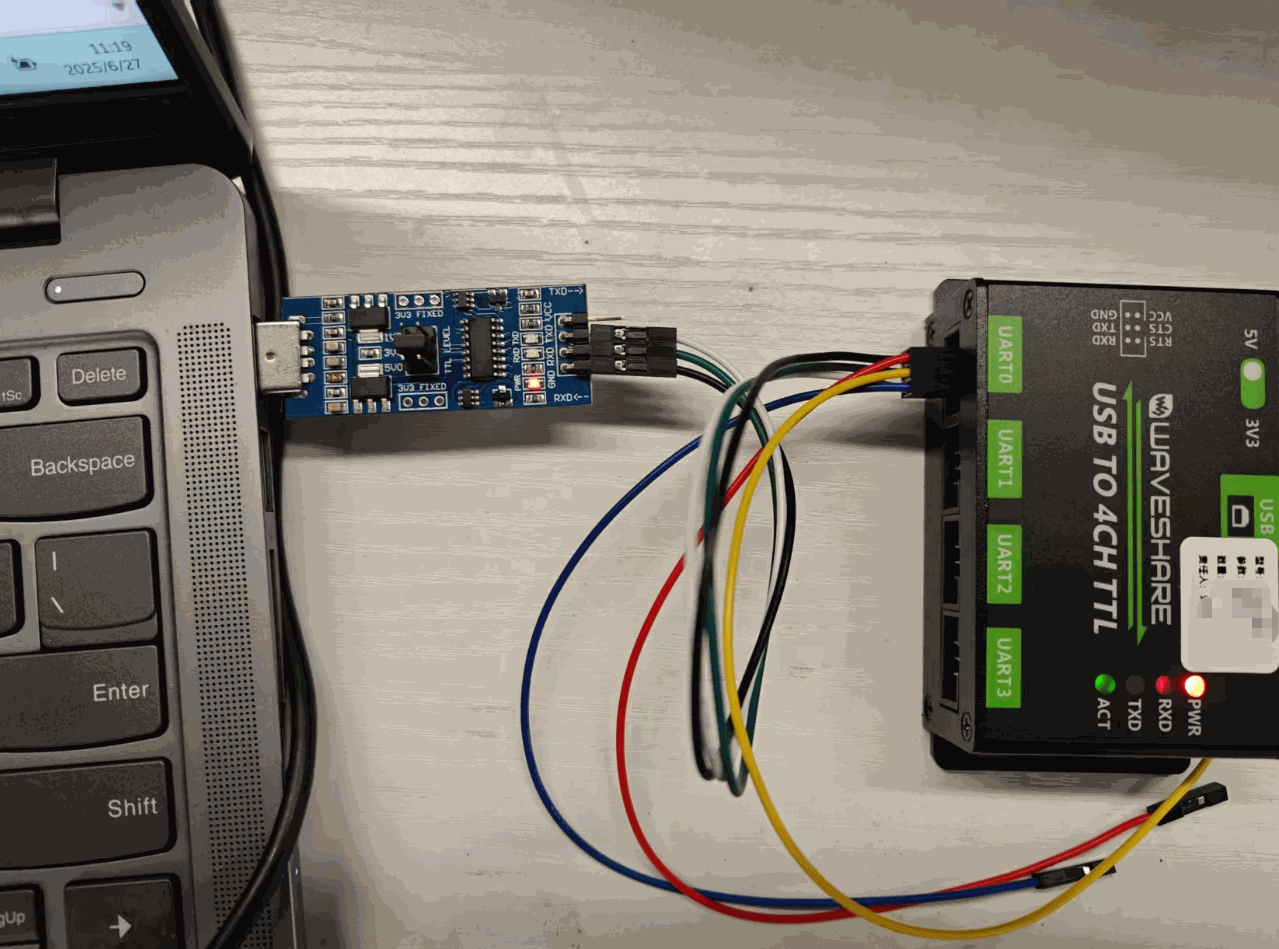
- Open the "serial debugging tool" on the Windows computer, open the corresponding serial port and set the baud rate (keep it consistent with the setting in the AidLux terminal)
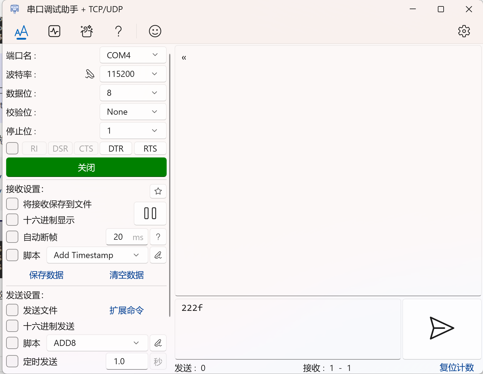
- After both the "serial debugging tool" on the Windows side and the terminal on the AidLux side are set up, you can proceed with send and receive message tests.
AidLux Receive Test
Execute the command in the AidLux terminal to view the received messages.
sudo cat /dev/ttyCH343USB0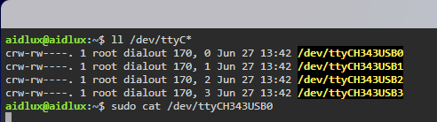
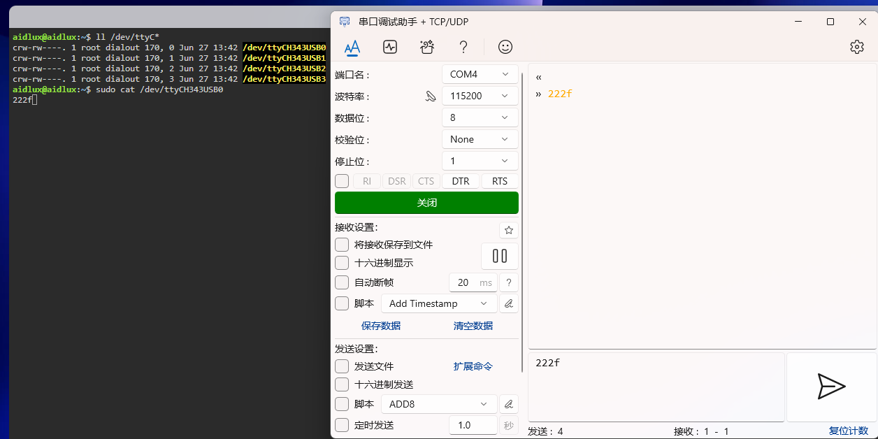
Send messages on the "serial debugging tool" on the Windows computer, and you can see that AidLux receives the messages.
AidLux Send Test:
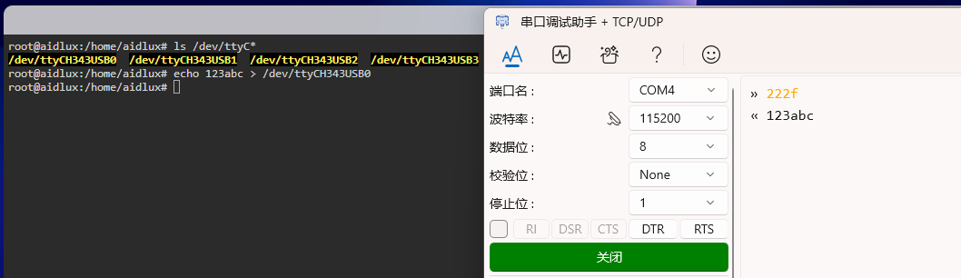
Execute the command in the AidLux terminal to send messages, and you can see that the "serial debugging tool" receives the messages.
echo 123abc > /dev/ttyCH343USB0Note
If a permission error is prompted, execute the command sudo su to switch to the root user before testing. The password is required: aidlux
USB TO 8CH TTL
- Official kit documentation: USB TO 8CH TTL
Preparation
- Rhino Pi-A1
- USB TO 8CH TTL serial device
- CH340 USB TO TTL test board
- Several jumper wires
- Windows computer
Hardware Connection
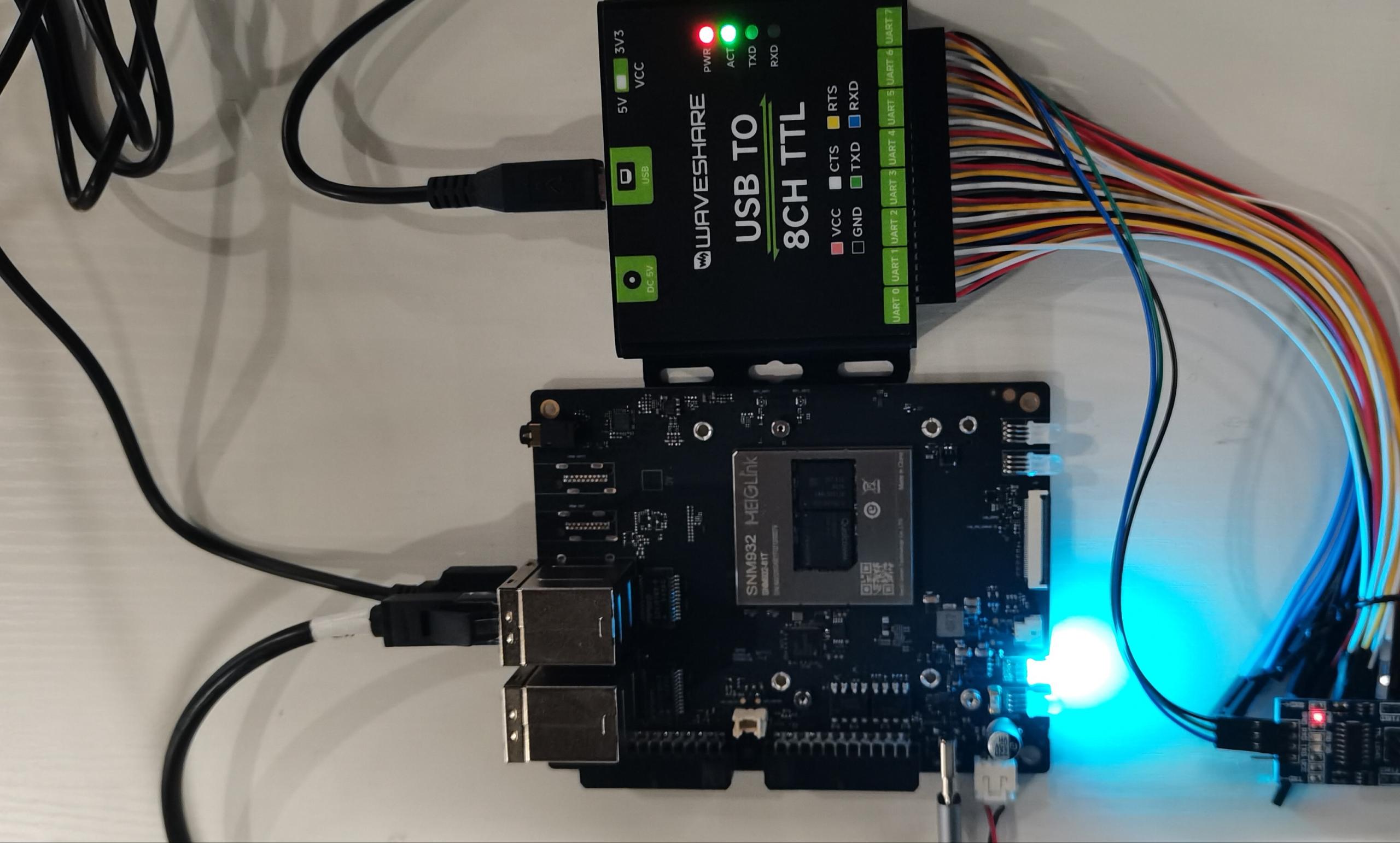
- Connect the development board to the CH348 device via a USB interface, and connect the CH340 test board to the Windows computer USB port and the CH348 device
Where: the RXD, TXD, and GND of the CH348 connect to the TXD, RXD, and GND of the CH340
Testing
Note
When executing commands in the terminal on the AidLux desktop, if the aidlux password is required, enter: aidlux
After obtaining the IP address of the Rhino Pi-A1, log in to the AidLux Web desktop via the browser.
After logging in, enter the following command in the AidLux terminal to check whether the CH348 serial device has been recognized.
ls -l /dev/ttyC*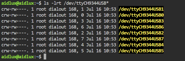
Note
The multi-channel serial device names of the CH348 correspond one-to-one to the actual physical UART interface names, i.e., /dev/ttyCH9344USB0 corresponds to UART0; /dev/ttyCH9344USB1 corresponds to UART1, and so on.
- Install the minicom tool
minicom is not installed on AidLux by default. You can install it with the following command:
sudo apt update
sudo apt install minicom- Use the minicom tool on the Rhino Pi-A1 to open the serial device
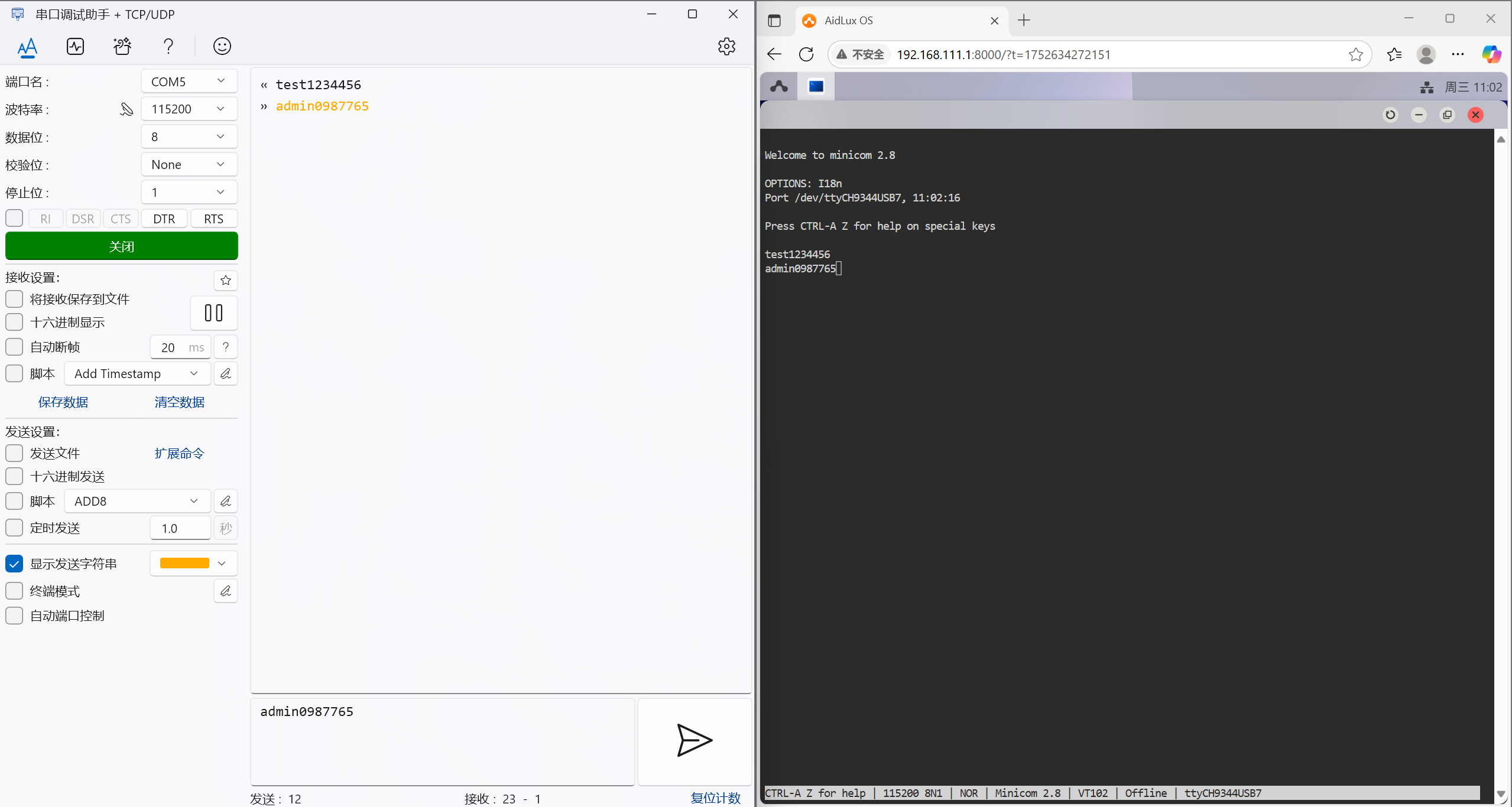
If the current CH348 is connected to the UART7 port, execute the following command to open the serial device:
sudo minicom -D /dev/ttyCH9344USB7 -b 115200- Use the serial debugging tool on the Windows side to open the serial device
Windows can install a serial debugging tool. After opening the tool, select the corresponding port and open it. Note: the baud rate must be consistent with that of the minicom tool on the Rhino Pi-A1 side, e.g., 115200.
- Send messages between both sides for testing
You can enter any characters in minicom to send for testing, and the Windows serial debugging tool can see the received messages; and vice versa.
Note
minicom does not display the input characters by default. You can press Ctrl-A, Z, E in sequence to set the display of input messages.
CH9102
Preparation
- Rhino Pi-A1
- CH9102 serial device
- CH340 USB TO TTL test board
- Several jumper wires
- Windows computer
Hardware Connection
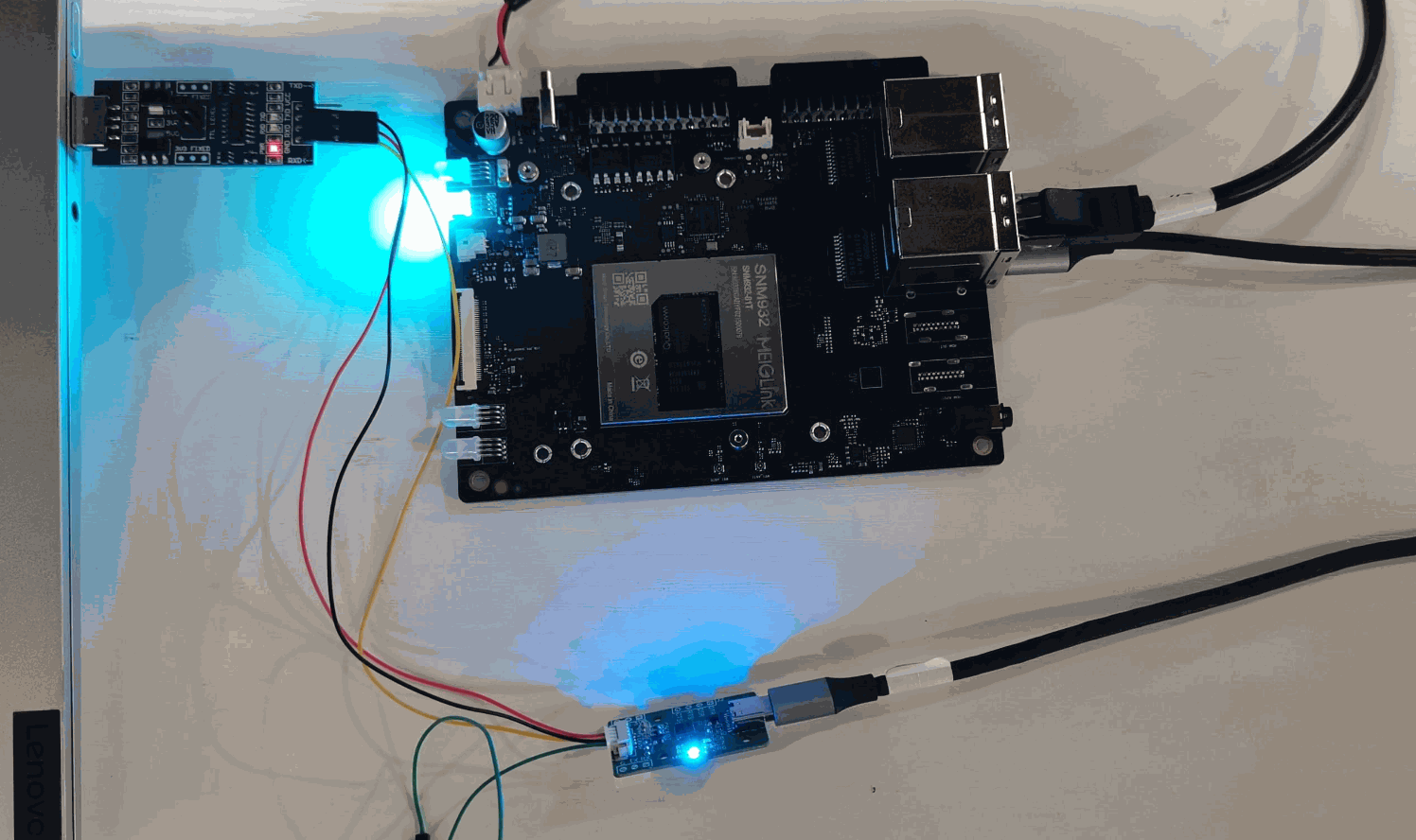
- Connect the development board to the CH9102 device via a USB interface, and connect the CH340 test board to the Windows computer USB port and the CH9102 device
Where: the RXD, TXD, and GND of the CH9102 connect to the TXD, RXD, and GND of the CH340
Testing
Note
When executing commands in the terminal on the AidLux desktop, if the aidlux password is required, enter: aidlux
After obtaining the IP address of the Rhino Pi-A1, log in to the AidLux Web desktop via the browser.
After logging in, enter the following command in the AidLux terminal to check whether the CH9102 serial device has been recognized.
ls -l /dev/ttyC*
- Use the stty tool to configure the serial device
chmod 777 /dev/ttyCH343USB0                              // grant permission to the serial device node
stty -F /dev/ttyCH343USB0 115200                         // set the serial device node baud rate
stty -F /dev/ttyCH343USB0 -isig -icanon iexten -echo // other settings- Use the serial debugging tool on the Windows side to open the serial device
Windows can install a serial debugging tool. After opening the tool, select the corresponding port and open it. Note: the baud rate must be consistent with that set by the stty tool on the Rhino Pi-A1 side, e.g., 115200.
- Send messages between both sides for testing
You can use the echo command to send characters to the serial device, and observe that the serial tool on the Windows side receives the messages; conversely, send characters in the serial tool on the Windows side, and the Rhino Pi-A1 side can receive them via the cat command.
Send command:
echo 'demo123' > /dev/ttyCH343USB0Receive command:
cat /dev/ttyCH343USB0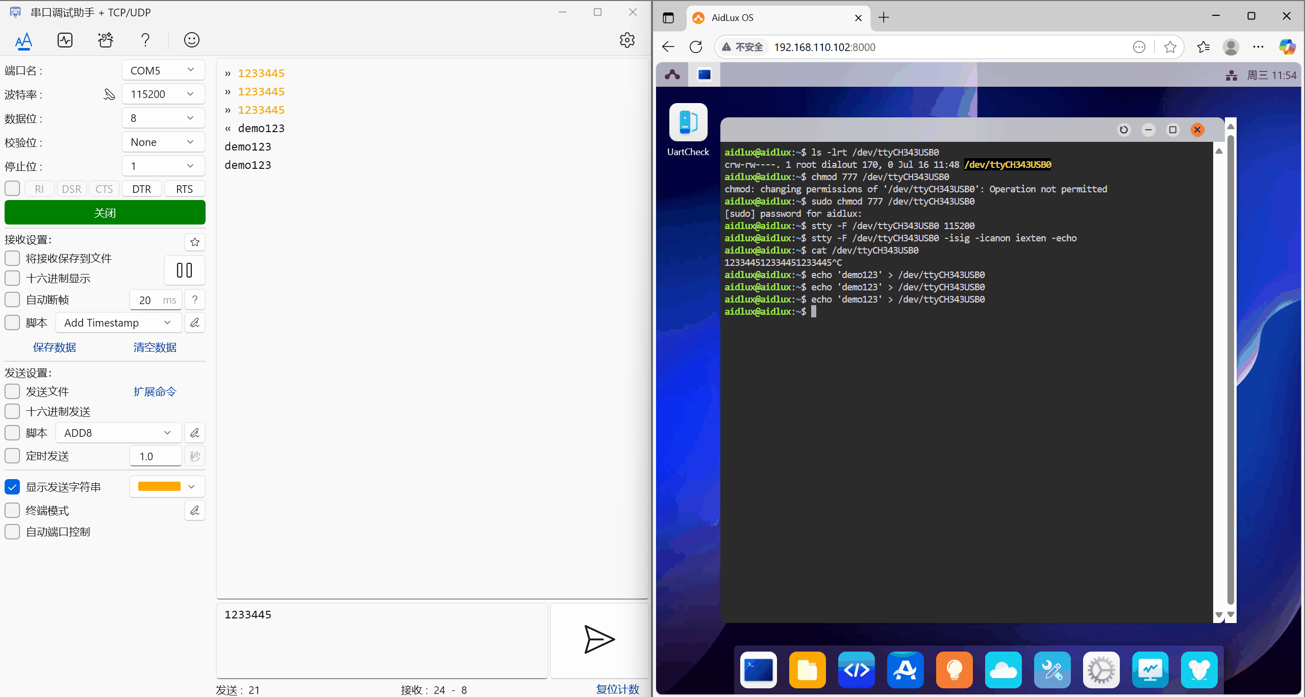
CP2102
- Official kit documentation: CP2102
Preparation
- Rhino Pi-A1
- CP2102 serial device
- CH340 USB TO TTL test board
- Several jumper wires
- Windows computer
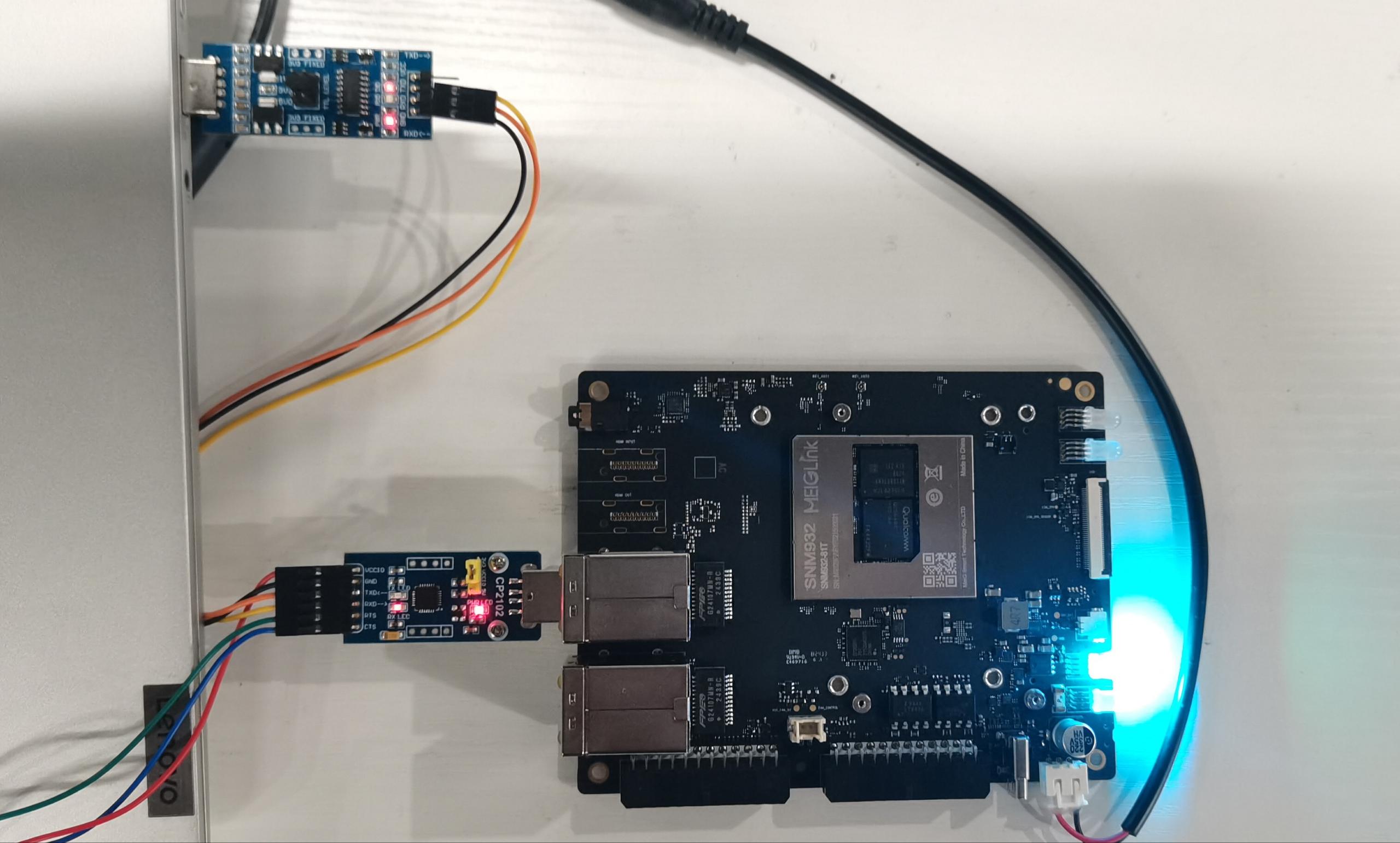
Hardware Connection
- Connect the development board to the CP2102 device via a USB interface, and connect the CH340 test board to the Windows computer USB port and the CP2102 device
Where: the RXD, TXD, and GND of the CP2102 connect to the TXD, RXD, and GND of the CH340
Testing
Note
When executing commands in the terminal on the AidLux desktop, if the aidlux password is required, enter: aidlux
After obtaining the IP address of the Rhino Pi-A1, log in to the AidLux Web desktop via the browser.
After logging in, enter the following command in the AidLux terminal to check whether the CP2102 serial device has been recognized.
ls -l /dev/ttyU*
- Use the stty tool to configure the serial device
chmod 777 /dev/ttyUSB0                              // grant permission to the serial device node
stty -F /dev/ttyUSB0 115200                         // set the serial device node baud rate
stty -F /dev/ttyUSB0 -isig -icanon iexten -echo // other settings- Use the serial debugging tool on the Windows side to open the serial device
Windows can install a serial debugging tool. After opening the tool, select the corresponding port and open it. Note: the baud rate must be consistent with that set by the stty tool on the Rhino Pi-A1 side, e.g., 115200.
- Send messages between both sides for testing
You can use the echo command to send characters to the serial device, and observe that the serial tool on the Windows side receives the messages; conversely, send characters in the serial tool on the Windows side, and the Rhino Pi-A1 side can receive them via the cat command.
Send command:
echo 'demo111' > /dev/ttyUSB0Receive command:
cat /dev/ttyUSB0