Interface Definition
Peripheral Interface Table
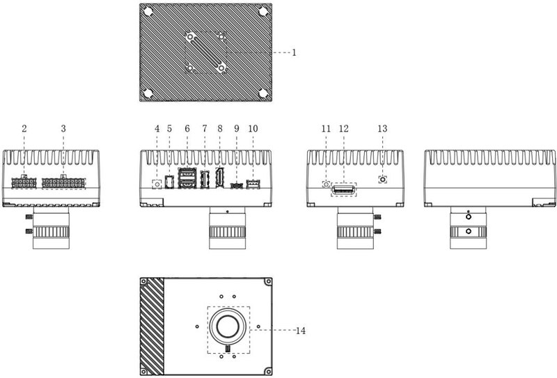
| No. | Name | Description |
|---|---|---|
| 1 | Mounting Screw Holes | 4 × M4 mounting screw holes, effective thread depth 8 mm, spacing: 26 × 26 mm |
| 2 | 10-PIN Interface | See Fig - Power and I/O Interface Definition |
| 3 | 20-PIN Interface | See Fig - Power and I/O Interface Definition |
| 4 | LED Indicator | Network port status indication |
| 5 | Ix Industrial LAN Port | Industrial IX Gigabit Ethernet port |
| 6 | USB Dual-Layer Interface | 2 × USB 2.0 Type-A |
| 7 | USB Side-Stand Interface | 1 × USB 2.0 Type-A |
| 8 | HDMI Side-Stand Interface | HDMI mini display output |
| 9 | Type-C Interface | 1 × Type-C OTG |
| 10 | Power Interface | DC 12V IN |
| 11 | LED Indicator | System status indication |
| 12 | Micro SD Interface | Expansion high-speed TF card storage interface |
| 13 | Power Button | Long press 15 s to reboot |
| 14 | C-Mount Lens | Lens focal length 4-20 mm selectable |
Power and IO Interface Definition
10-Pin and 20-Pin Definitions
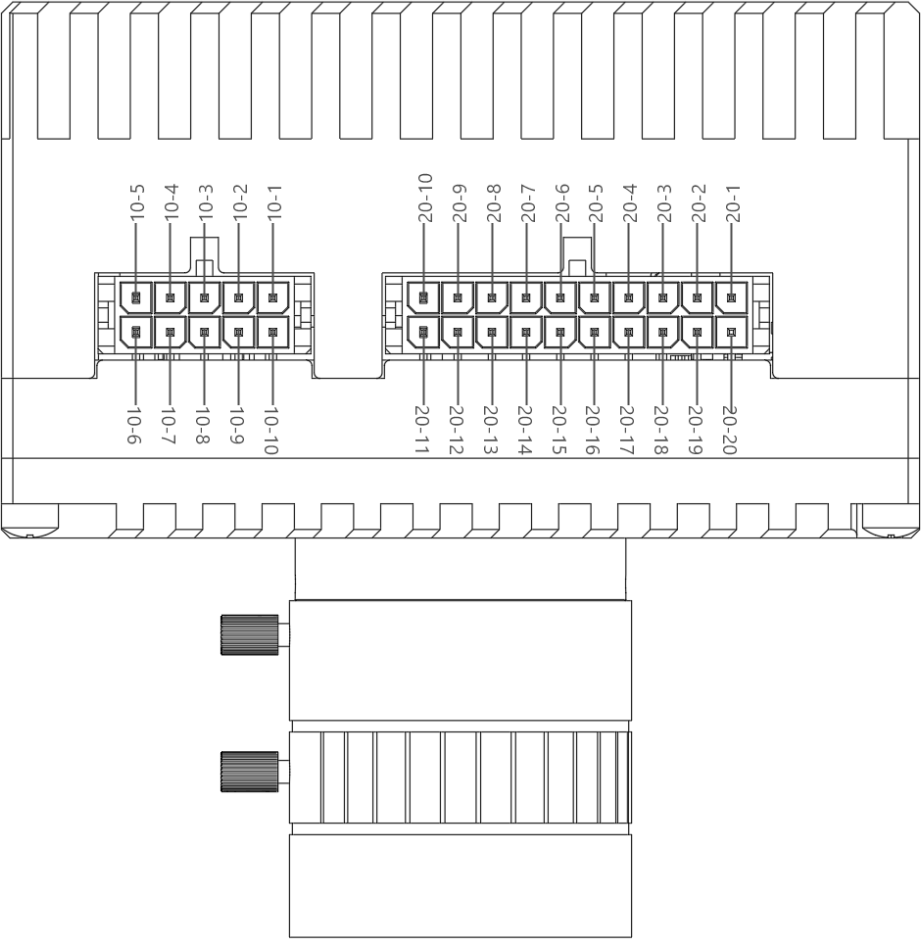
| Pin | Signal | I/O Signal Source | Description |
|---|---|---|---|
| 10-1 | CAN0 H | CAN0 | |
| 10-2 | CAN0_L | CAN0 | |
| 10-3 | GND | GND | |
| 10-4 | CAN1_H | CAN1 | |
| 10-5 | CAN1_L | CAN1 | |
| 10-6 | GND | GND | |
| 10-7 | RS485_M | RS485 | |
| 10-8 | RS485_P | RS485 | |
| 10-9 | GND | GND | |
| 10-10 | 5V | 5V Output | |
| 20-1 | GPIO_12 | SPI_MISO | SPI master device output (slave device input) |
| 20-2 | GPIO_13 | SPI_MOSI | SPI master device input (slave device output) |
| 20-3 | GPIO_14 | SPI_SCLK | SPI clock interface |
| 20-4 | GPIO_15 | SPI_CS_N | Chip select |
| 20-5 | GND | Ground | |
| 20-6 | GPIO_22 | SM_DBG_UART_TX | Debug UART transmit |
| 20-7 | GPIO_23 | SM_DBG_UART_RX | Debug UART receive |
| 20-8 | OUTPUT_GND | Optocoupler output ground | |
| 20-9 | GPIO_61 | OUTPUT_1P | Optocoupler output 1 |
| 20-10 | GPIO_6 | OUTPUT_2P | Optocoupler output 2 |
| 20-11 | GPIO_52 | INPUT_2P | Optocoupler input 2 |
| 20-12 | GPIO_81 | INPUT_1P | Optocoupler input 1 |
| 20-13 | INPUT_GND | Optocoupler input ground | |
| 20-14 | GPIO_98 | I2S_FS | I2S master clock (MCLK) |
| 20-15 | GPIO_100 | I2S_SCLK | I2S bit clock (SCK) |
| 20-16 | GPIO_97 | I2S_DIN | I2S word select (WS) |
| 20-17 | GPIO_96 | I2S_DOUT | I2S data channel (DATA) |
| 20-18 | GND | Ground | |
| 20-19 | UART0_TXD | Module serial TX | |
| 20-20 | UART0_RXD | Module serial RX |
Peripheral Devices
Camera
- C-Mount Lens: Lens focal length 4-20 mm selectable
Display
- HDMI mini: HDMI mini display output interface
GPIO
- Optocoupler Isolated Input: 2 channels (INPUT_1P / INPUT_2P), for details see Board Hardware - Interfaces
- Optocoupler Isolated Output: 2 channels (OUTPUT_1P / OUTPUT_2P), for details see Board Hardware - Interfaces
I2C
TBD.
SPI
TBD.