Interface Definition
Peripheral Interface Table
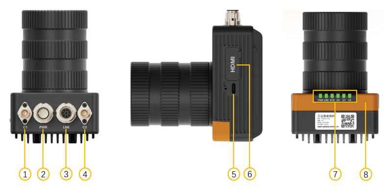
| Interface No. | Interface Name | Function Description |
|---|---|---|
| 1 | C1 | Camera 1 |
| 2 | POWER | IO 17-Pin interface, see "IO 17-PIN Definition Table" |
| 3 | LINK | Aviation plug to Ethernet adapter |
| 4 | C2 | Camera 2 |
| 5 | Type-C | Type-C interface |
| 6 | HDMI | HDMI display interface |
| 7 | Indicators | PWR/LNK/SYS/C0/C1/C2 |
| 8 | WIFI/BT | WIFI/BT protective cover, WIFI/BT antenna hidden beneath |
IO 17-PIN Definition Table
The power & IO aviation interface, cable, and pin definitions are as follows. The housing uses an M12 male connector.
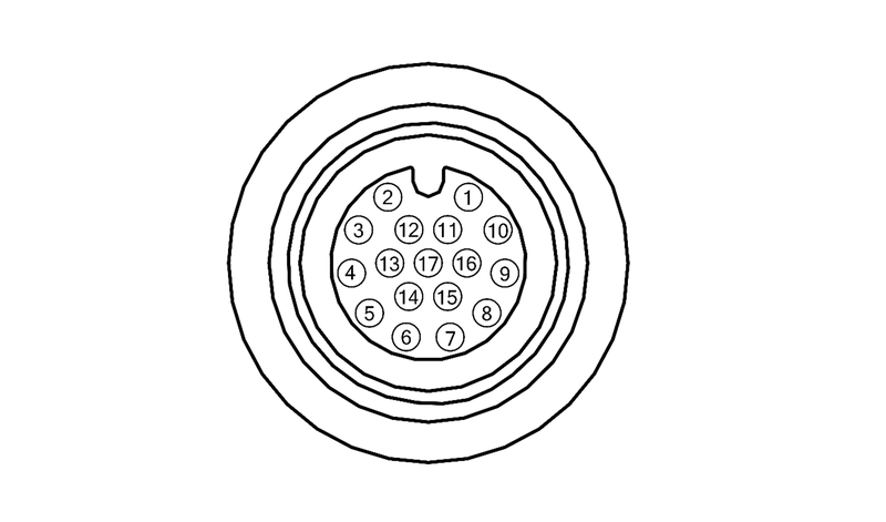
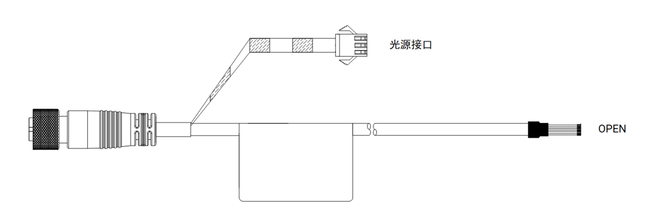
| Pin | Signal | I/O Signal Source | Description | Cable Color Reference (subject to actual label) |
|---|---|---|---|---|
| 1 | VCC+ | NA | DC Power + | Green |
| 2 | VCC+ | NA | DC Power + | Green-White |
| 3 | VCC- | NA | Power Ground | Brown |
| 4 | VCC- | NA | Power Ground | White |
| 5 | LED+ | NA | External Light Source + | Red |
| 6 | LED- | NA | External Light Source - | Black |
| 7 | RS485_A | NA | RS485_A | Yellow |
| 8 | RS485_B | NA | RS485_B | Yellow-White |
| 9 | OPTO_IN0 | Line0 + | Opto-isolated Input 0+ | Orange |
| 10 | OPTO_IN1 | Line1 + | Opto-isolated Input 1+ | Orange-White |
| 11 | IN_COM0 | Line0/1/2 - | Opto-isolated Input 0/1/2 - | Purple |
| 12 | OPTO_OUT0 | Line4 + | Opto-isolated Output 4+ | Purple-White |
| 13 | OPTO_OUT1 | Line5 + | Opto-isolated Output 5+ | Blue |
| 14 | OUT_COM0 | Line3/4/5/6 - | Opto-isolated Output - | Pink |
| 15 | OPTO_OUT2 | Line3 + | Opto-isolated Output 3+ | Brown-White |
| 16 | OPTO_IN2 | Line2 + | Opto-isolated Input 2+ | Blue-White |
| 17 | OPTO_OUT3 | Line6 + | Opto-isolated Output 6+ | Gray |
⚠ Warning
- The sub-wire colors of the 17 PIN cable may vary by production batch. Please refer to the actual label colors. This document provides reference only!
- Some batches of the 17 PIN cable have LED+ and LED- paralleled into a separate terminal. It is not recommended to use this together with the LED+ and LED- in the 17 PIN connector, as using both parallel light source outputs simultaneously may result in insufficient power.
Network Port Aviation Header Pin Definition
The 8-PIN interface on the camera housing uses an M12 female connector.
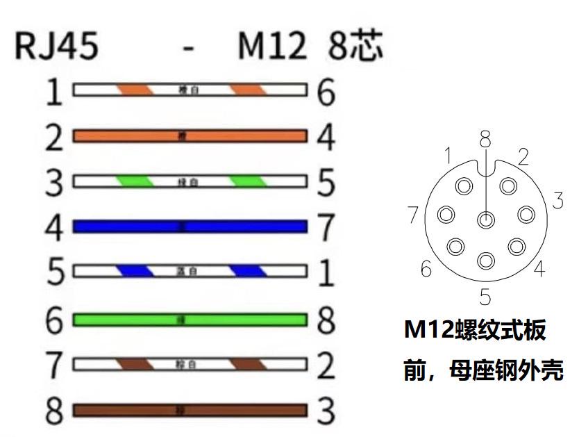
Peripheral Devices
Camera
| Item | Specification |
|---|---|
| Camera Configuration | 1x Main Camera (optional) + 2x GMSL Sub-Cameras (optional) |
| Lens Mount | C-Mount, with lens protective cover |
Comparison of the two optional sensors:
| Parameter | SC535HGS | SC880sl |
|---|---|---|
| Sensor Type | CMOS, Global shutter, Color | CMOS, Rolling shutter, Color |
| Sensor Size | 2/3" | 1/1.2" |
| Pixel Size | 3.45μm | 2.988μm |
| Max Resolution | 2448×2048 | 3840×2160 |
| Max Frame Rate | 80 FPS | 60 FPS |
| CRA | 0° | 9° |
Display
- 1x HDMI port, supports external display connection
Bluetooth
The camera supports Bluetooth (classic/BLE). You can use the bluetoothctl command to turn Bluetooth on/off, scan, pair, and connect devices. The Bluetooth stack is BlueZ 5.64.
Turn On Bluetooth
bluetoothctl power onCheck Status
bluetoothctl show          # View controller (powered/name/address)
hciconfig -a               # View hci0 status
bluetoothctl devices       # View paired devices
Scan
bluetoothctl               # Enter interactive mode
scan on                    # Start scanning (BLE + classic)
devices                    # List discovered devices
scan off                   # Stop scanning (for viewing only; keep scan on when pairing, see next step)
Classic Bluetooth only (requires root):
sudo hcitool scan           # Classic Bluetooth
sudo hcitool lescan         # Low Energy BLE
Connect and Use
⚠️ Note
Before pairing, put the target device into pairing mode (e.g., K380 keyboard: long-press F1/F2/F3 for 3 seconds until the indicator blinks rapidly); otherwise pair will report Device not available.
bluetoothctl               # Enter interactive mode
scan on                    # Start scanning (keep it on when pairing; do not scan off, otherwise the cache will be cleared)
pair <MAC>                 # Pair, e.g., pair F4:73:35:8B:B7:12
                           #   If a Passkey is prompted (e.g., 162375), type the 6-digit number on the keyboard and press Enter
trust <MAC>                # Trust (avoid repeated confirmation)
connect <MAC>              # Connect (after pairing, use this command to reconnect later)
Disconnect / remove:
disconnect <MAC>           # Disconnect
remove <MAC>               # Remove device
Turn Off Bluetooth
bluetoothctl power off💡 Tip
Low-level commands such as hcitool require sudo; bluetoothctl can be used by regular users.
4G Module
The camera supports an external 4G module for cellular network access. The following describes how to test the external 4G module.
Hardware Preparation
- The 4G module requires a separate power supply.
- USB adapter: one end of the micro cable connects to the 4G module, and the other end connects to the USB adapter, which is then plugged into the camera.
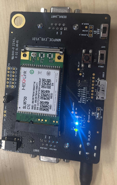
Test Steps
Download the firmware to the camera, then power on and enter the system.
Connect the PC and the camera to the same WiFi network.
Connect to the camera via WiFi ADB:
Connect the camera to the PC via a Type-C cable.
Get the device WiFi IP address:
bashadb shell ifconfig wlan0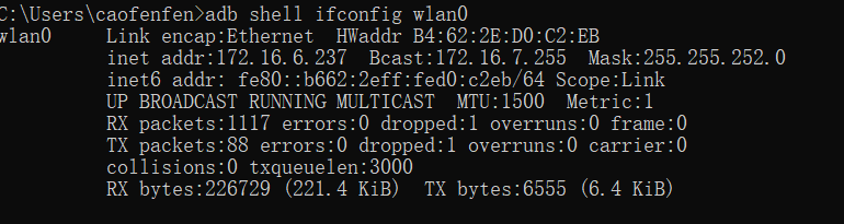
Switch to TCP mode:
bashadb root adb tcpip 5555Connect to the device IP:
bashadb connect <device-ip>:5555
Disconnect the Type-C cable between the camera and the PC.
Connect the 4G module to the camera via the USB adapter.
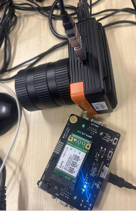
Run
lsusbto check whether the 4G module is mounted. If05c6:f601appears, the module is mounted successfully:bashlsusb
Run
ifconfigto check whether theusb0network interface appears:bashifconfig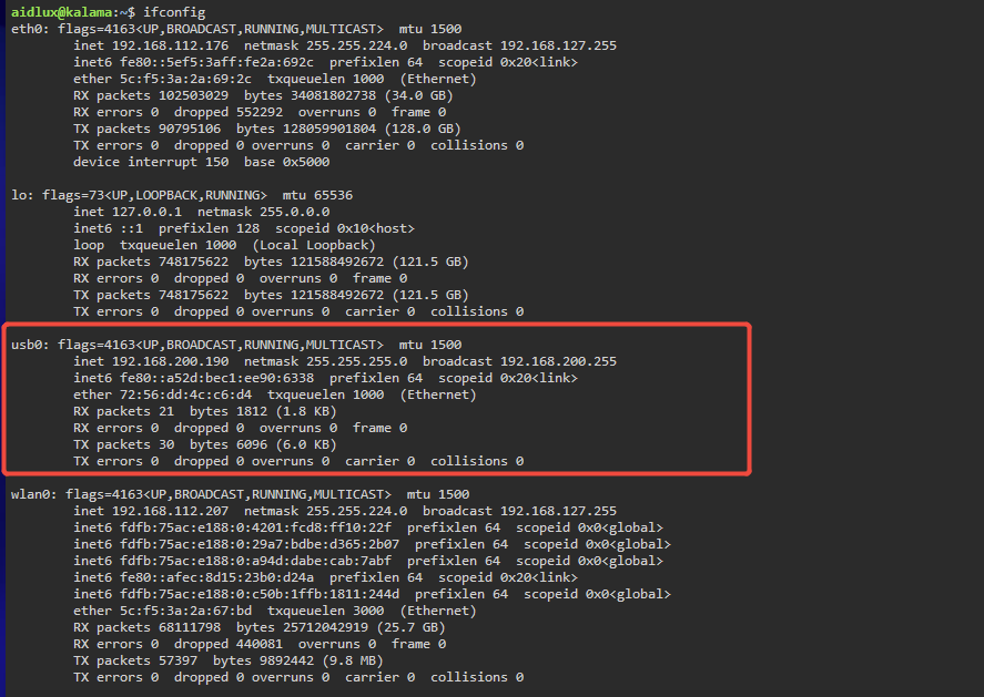
Ping an external network through the 4G module's network interface. If the ping succeeds, communication is working:
bashping -I usb0 www.baidu.com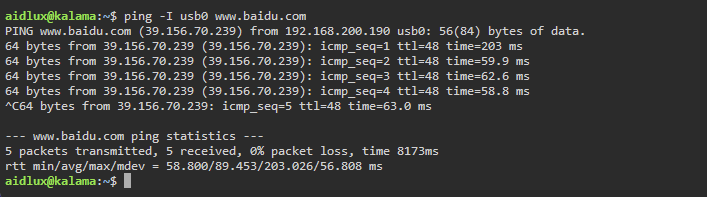
GPIO
- 3x Opto-isolated Input (Line0/Line1/Line2) + 1x Input Ground
- 4x Opto-isolated Output (Line3/Line4/Line5/Line6) + 1x Output Ground
- 1x RS485
See Board Hardware — Interfaces.
RS-485
⚠ Note
The camera's RS-485 interface is currently a 2-wire serial port without flow control, which may cause significant packet loss (20%+) during transmission and reception. Run the following command to restore the serial port to a "no packet loss" reliable communication mode (takes effect immediately).
Run the following command on the device:
stty -F /dev/ttyHS1 9600 cs8 -parenb -cstopb -echo -echoe -echok -echoctl -echoke -icanon -iexten -isig -opost -onlcr -ocrnl -onocr -icrnl -ixon -ixoff -ixany -crtscts rawI2C
To be added.
SPI
To be added.