Rhino A1 Mini Carrier Board Introduction
Product Overview
The Rhino A1 Mini carrier board is equipped with the Rhino Core Q64 smart module. The carrier board provides a 1G RJ45 port, Wi-Fi 6 / Bluetooth 5.4, 4 × USB Type-A, Micro HDMI, MIPI DSI and dual MIPI CSI interfaces. The 40-pin expansion header provides I2C, I2S, SPI, UART and GPIO signals; the PCIe FPC connector supports external PCIe devices; and the Micro SD / TF card socket can be used for storage expansion. PoE power requires a compatible HAT.
The 85 mm × 56 mm board outline makes it easy to integrate into space-constrained devices, and is suitable for digital signage, touch-interactive terminals, robot perception, industrial vision and edge AI application development.
Product Appearance
Photo of the Rhino A1 Mini carrier board: 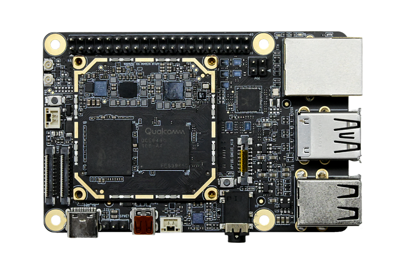
Interface Diagrams
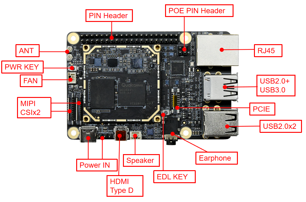
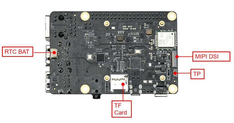
Physical Dimensions
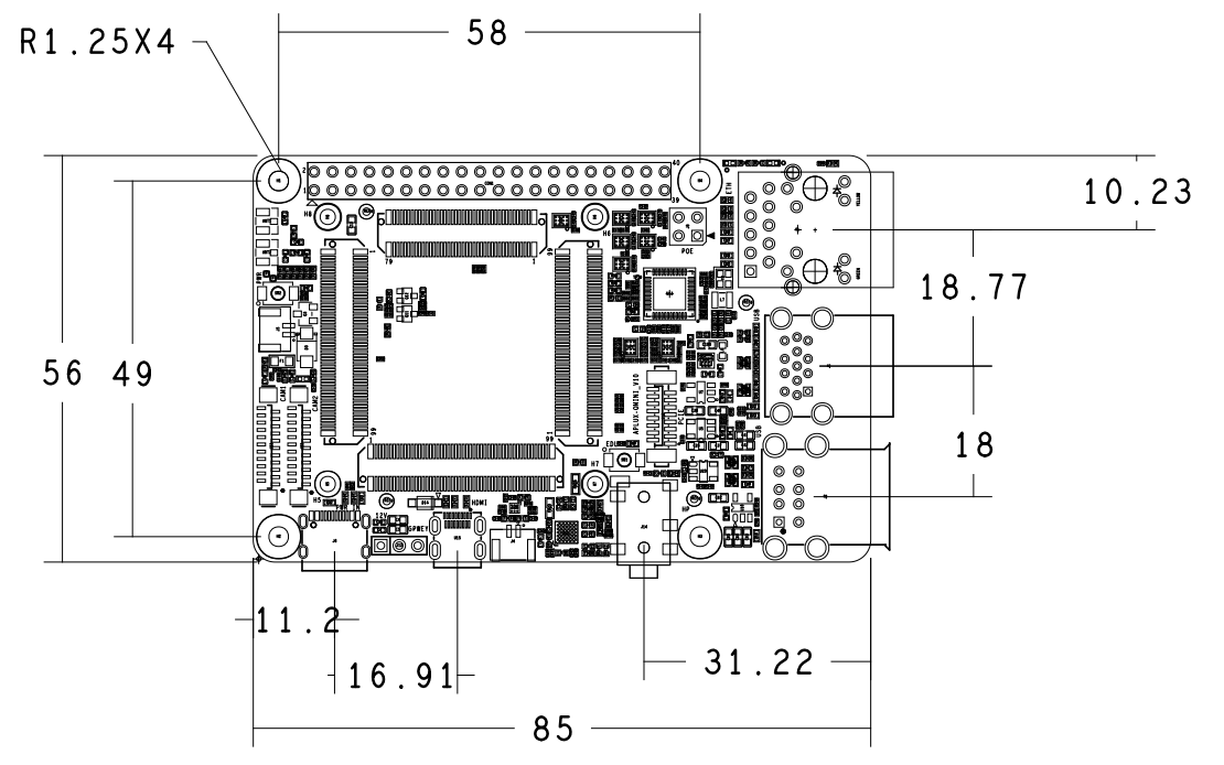
| Item | Parameter |
|---|---|
| Board outline reference size | 85mm × 56mm (±0.5mm) |
| PCB thickness | 1.2mm (±10%) |
| Mounting hole specification | Φ2.5mm × 4 (±10% on hole diameter, marked R1.25 × 4) |
For detailed dimension information, contact the APLUX FAE to obtain the DXF document. Enclosure design should also account for connector protrusions and assembly clearance.
Specification List
| Category | Specification |
|---|---|
| Core Board | Rhino Core Q64 Smart Module (A6490MA1) |
| Memory / Storage | 8GB LPDDR5 + 64GB eMMC 5.1 (actual configuration subject to order) |
| TF Card | Plug-in TF card socket |
| USB | 4 × USB Type-A: 1 × USB 3.0 + 3 × USB 2.0 |
| Display | Micro HDMI (Type D) connector; MIPI DSI display interface |
| Camera | 2 × MIPI CSI, both 4-lane, 22-pin FPC connectors |
| Ethernet | 1 × Gigabit RJ45; PoE power requires a compatible HAT |
| Wireless | Wi-Fi 6 / Bluetooth 5.4, onboard FCU760K module |
| PCIe | 1 × PCIe, 16-pin FPC connector |
| Expansion | 40-pin, 2.54mm dual-row header (I2C, I2S, SPI, UART, GPIO) |
| Buttons | Flashing key (RECOVERY) and power key |
| Power Input | 12V/2A, Type-C interface or J12 pin header (do not use both at the same time) |
| Debug | External 3.3V serial debug support |
| Environment | Operating temperature reference range -20°C ~ 50°C, humidity 0%~95% (non-condensing) |
| Dimensions | Board outline reference size 85mm × 56mm |
Functions and Interface Definitions
J6 & J12 Power Input Interfaces
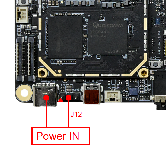
The board is powered through the J6 Type-C interface or the J12 pin header, with a reference power configuration of 12V/2A. The two inputs must not be used at the same time. When using a Type-C adapter, make sure it can supply 12V and at least 2A to the board, and use adapters and cables validated with the board. When powering external devices at the same time, verify the overall power budget.
[J6] Type-C power input interface.
[J12] 1×3-pin, 2.54mm pin header, where PIN3 is PWR_KEY and can be connected to an external power button.
PIN Definition:
| Pin# | Definition | Note |
|---|---|---|
| 1 | VCC_12V | 12V input |
| 2 | GND | Digital ground |
| 3 | PWR_KEY | Power-on signal |
J11 RTC Interface
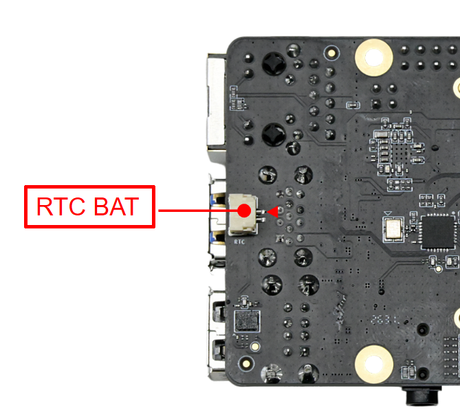
[J11] RTC backup battery interface. An external backup battery is required to use the RTC function. It is a 1×2×1.25mm locking connector, manufacturer: JST, model: SM02B-GHS-TB(LF)(SN).
PIN Definition:
| Pin# | Definition | Note |
|---|---|---|
| 1 | GND | Digital ground |
| 2 | VBAT | RTC battery |
J5 FAN Interface
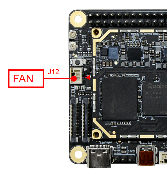
The J5 interface outputs 5V to the fan, with a maximum output current of 1A. The fan load should be included in the overall power budget.
[J5] Fan power socket (1×2-pin, 1.25mm), manufacturer: XUNPU, model: WAFER-GH1.25-2PLB.
PIN Definition:
| Pin# | Definition | Note |
|---|---|---|
| 1 | 5V | 5V DC power output |
| 2 | GND | Power ground |
J7 TF Card Socket
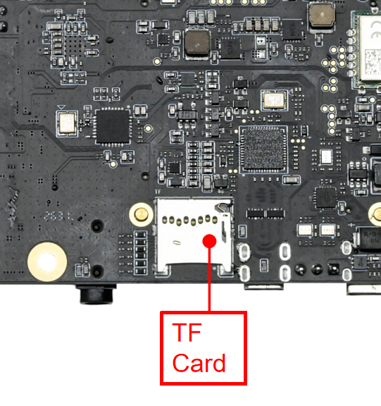
[J7] Plug-in standard TF card socket, supporting SD v3.0 (backward compatible with 2.0).
J1 & J2 USB Interfaces
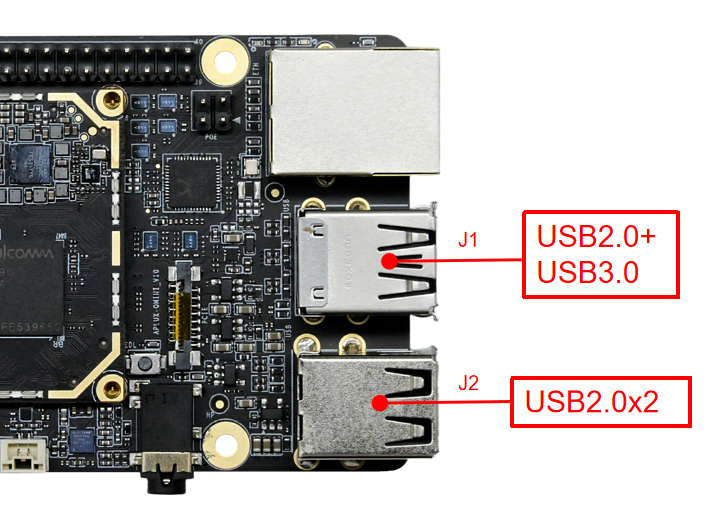
J1 is a dual-deck Type-A interface providing one USB 2.0 and one USB 3.0 port. The USB 2.0 port is expanded through an onboard USB 2.0 hub, while the USB 3.0 port uses the SoC's native path; each port has its own load switch with a 1.2A current limit.
J2 provides two USB 2.0 ports expanded through the hub; both ports share one load switch with a combined 1A current limit. The actual available power per port is also constrained by the overall system power budget.
U15 Micro HDMI Connector
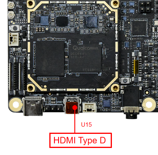
[U15] Micro HDMI connector (HDMI Type D interface).
J55 MIPI DSI Interface
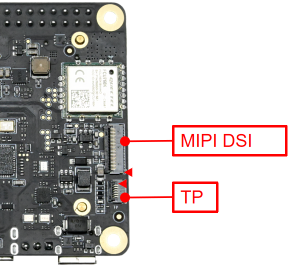
[J55] The DSI interface is 4lane, using a double-sided-contact, flip-type 31PIN FPC connector. Manufacturer: HRS, model: FH35C-31S-0.3SHW(50).
PIN Definition:
| Pin# | Definition | Note |
|---|---|---|
| 1 | LEDA | Backlight anode |
| 2 | LEDA | Backlight anode |
| 3 | LEDA | Backlight anode |
| 4 | - | - |
| 5 | - | - |
| 6 | LEDK | Backlight cathode |
| 7 | LEDK | Backlight cathode |
| 8 | LEDK | Backlight cathode |
| 9 | GND | Digital ground |
| 10 | GND | Digital ground |
| 11 | LN2_P | MIPI DSI data signal |
| 12 | LN2_M | MIPI DSI data signal |
| 13 | GND | Digital ground |
| 14 | LN1_P | MIPI DSI data signal |
| 15 | LN1_M | MIPI DSI data signal |
| 16 | GND | Digital ground |
| 17 | CLK_P | MIPI DSI clock signal |
| 18 | CLK_M | MIPI DSI clock signal |
| 19 | GND | Digital ground |
| 20 | LN0_P | MIPI DSI data signal |
| 21 | LN0_M | MIPI DSI data signal |
| 22 | GND | Digital ground |
| 23 | LN3_P | MIPI DSI data signal |
| 24 | LN3_M | MIPI DSI data signal |
| 25 | GND | Digital ground |
| 26 | - | - |
| 27 | Reset | Display reset signal |
| 28 | - | - |
| 29 | VDD1V8 | LCD 1.8V IO power |
| 30 | 3V3_LCD | LCD 3.3V power |
| 31 | 3V3_LCD | LCD 3.3V power |
[J13] is the TP connector supporting I2C, using a flip-type FPC connector. Manufacturer: HRS, model: FH34SRJ-6S-0.5SH(50).
PIN Definition:
| Pin# | Definition | Note |
|---|---|---|
| 1 | I2C_SCL | I2C clock signal, 3.3V |
| 2 | I2C_SDA | I2C data signal, 3.3V |
| 3 | GND | Digital ground |
| 4 | TP_RST | TP reset signal |
| 5 | TP_INT | TP interrupt signal |
| 6 | VCC_3V3 | 3.3V power output |
J22 & J23 Camera Connectors
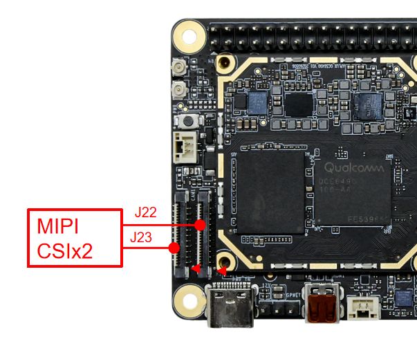
J22 & J23 are camera connectors with identical signal definitions, both supporting MIPI 4Lane CSI with up to 2.5Gbps per lane. They are 1×22×0.5mm vertical drawer-type FPC connectors. Manufacturer: HDGC, model: 0.5K-A-22PB.
PIN Definition:
| Pin# | Definition | Note |
|---|---|---|
| 1 | GND | Digital ground |
| 2 | LN0_M | Differential data signal |
| 3 | LN0_P | Differential data signal |
| 4 | GND | Digital ground |
| 5 | LN1_M | Differential data signal |
| 6 | LN1_P | Differential data signal |
| 7 | GND | Digital ground |
| 8 | CLK_M | Differential clock signal |
| 9 | CLK_P | Differential clock signal |
| 10 | GND | Digital ground |
| 11 | LN2_M | Differential data signal |
| 12 | LN2_P | Differential data signal |
| 13 | GND | Digital ground |
| 14 | LN3_M | Differential data signal |
| 15 | LN3_P | Differential data signal |
| 16 | GND | Digital ground |
| 17 | RST | Reset signal |
| 18 | LED | LED signal |
| 19 | GND | Digital ground |
| 20 | SCL | I2C bus clock signal |
| 21 | SDA | I2C bus data signal |
| 22 | CAM_3V3 | 3.3V power output |
J3 Ethernet Port
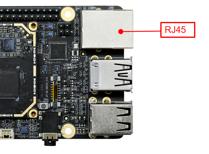
[J3] 1G Ethernet port with POE; the POE function requires a HAT.
J10 PCIe Interface
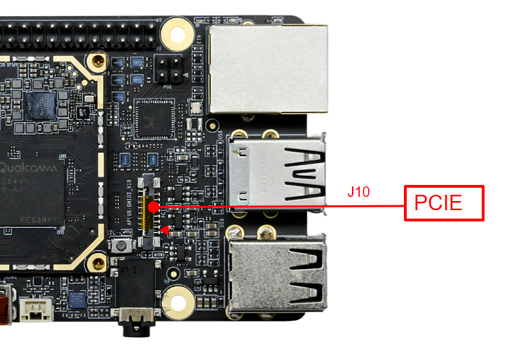
[J10] is a PCIe interface using a vertical drawer-type FPC connector. Manufacturer: XUNPU, model: FPC-0.5AL-16PB.
PIN Definition:
| Pin# | Definition | Note |
|---|---|---|
| 1 | PCIE_5V | 5V output, can power PCIe peripherals, 1.2A |
| 2 | PCIE_5V | - |
| 3 | GND | Digital ground |
| 4 | PCIE_CLK_P | PCIe clock signal |
| 5 | PCIE_CLK_N | - |
| 6 | GND | Digital ground |
| 7 | PCIE_RX_P | PCIe data receive signal |
| 8 | PCIE_RX_N | - |
| 9 | GND | Digital ground |
| 10 | PCIE_TX_P | PCIe data transmit signal |
| 11 | PCIE_TX_N | - |
| 12 | GND | Digital ground |
| 13 | PCIE_PWR_EN | PCIe peripheral power enable signal |
| 14 | PCIE_DET_WAKE | PCIe wake signal |
| 15 | PCIE_CLKREQ_N | PCIe clock request signal |
| 16 | PCIE_RST_B | PCIe reset signal |
CON1 Expansion Interface
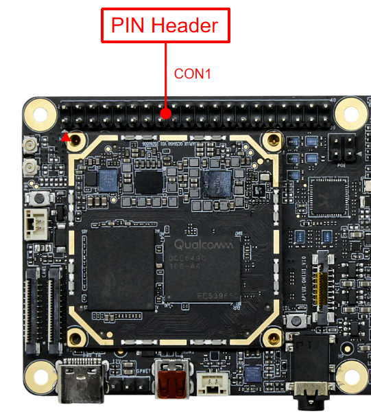
[CON1] External expansion interface, using a 40PIN 2.54mm pitch dual-row header. It can expand I2C, I2S, SPI and UART functions, and can also be used as GPIO. The interface level is 3.3V.
PIN Definition:
| Pin# | Definition | Note |
|---|---|---|
| 1 | VCC_3V3 | 3.3V output |
| 2 | VCC_5V_EXT | 5V output |
| 3 | GPIO44_I2C_SDA_3V3 | GPIO44, default I2C0 |
| 4 | VCC_5V_EXT | 5V output |
| 5 | GPIO45_I2C_SCL_3V3 | GPIO45, default I2C0 |
| 6 | GND | Digital ground |
| 7 | GPIO96_MI2S0_MCLK_3V3 | GPIO96, default I2S |
| 8 | DEBUG_UART_TX_3V3 | Debug serial |
| 9 | GND | Digital ground |
| 10 | DEBUG_UART_RX_3V3 | Debug serial |
| 11 | GPIO25_SPI_MOSI_3V3 | GPIO25, default SPI0 |
| 12 | GPIO97_MI2S0_SCLK_3V3 | GPIO97, default I2S |
| 13 | GPIO16_I2C_SDA_3V3 | GPIO16, default I2C1 |
| 14 | GND | Digital ground |
| 15 | GPIO17_I2C_SCL_3V3 | GPIO17, default I2C1 |
| 16 | GPIO6_UART1_TX_3V3 | GPIO6, default serial ttyHS0 |
| 17 | VCC_3V3 | 3.3V output |
| 18 | GPIO7_UART1_RX_3V3 | GPIO7, default serial ttyHS0 |
| 19 | GPIO49_SPI1_MOSI_3V3 | GPIO49, default SPI1 |
| 20 | GND | Digital ground |
| 21 | GPIO48_SPI1_MISO_3V3 | GPIO48, default SPI1 |
| 22 | GPIO57_FP_SPI_MOSI_3V3 | GPIO57, default SPI2 |
| 23 | GPIO50_SPI1_CLK_3V3 | GPIO50, default SPI1 |
| 24 | GPIO51_SPI1_CS0_N_3V3 | GPIO51, default SPI1 |
| 25 | GND | Digital ground |
| 26 | GPIO55_SPI1_CS1_N_3V3 | GPIO55, default SPI1 |
| 27 | GPIO0_I2C_SDA_3V3 | GPIO0, default I2C2 |
| 28 | GPIO1_I2C_SCL_3V3 | GPIO1, default I2C2 |
| 29 | GPIO27_SPI_CS_3V3 | GPIO27, default SPI0 |
| 30 | GND | Digital ground |
| 31 | GPIO24_SPI_MISO_3V3 | GPIO24, default SPI0 |
| 32 | GPIO26_SPI_SCLK_3V3 | GPIO26, default SPI0 |
| 33 | GPIO56_FP_SPI_MISO_3V3 | GPIO56, default SPI2 |
| 34 | GND | Digital ground |
| 35 | GPIO100_MI2S0_WS_3V3 | GPIO100, default I2S |
| 36 | GPIO59_FP_SPI_CS_3V3 | GPIO59, default SPI2 |
| 37 | GPIO58_FP_SPI_CLK_3V3 | GPIO58, default SPI2 |
| 38 | GPIO98_MI2S0_DATA0_3V3 | GPIO98, default I2S |
| 39 | GND | Digital ground |
| 40 | GPIO99_MI2S0_DATA1_3V3 | GPIO99, default I2S |
Note:
- All the above function pins can be configured as GPIO with a 3.3V level; ensure level matching when connecting external devices. The exact function depends on the system version and pin multiplexing settings; power and ground pins are not used as GPIO.
- The 3.3V and 5V outputs can supply up to 1A in total on each power rail, which must be shared across the corresponding rail; it must not be counted as 1A per power pin.
- The I2C, SPI and UART numbers above are the port numbers in the system.
J14 4-Pole Headset Jack
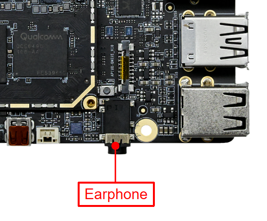
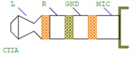
[J14] 4-pole 3.5mm headphone/microphone jack (CTIA standard).
J4 Speaker Interface
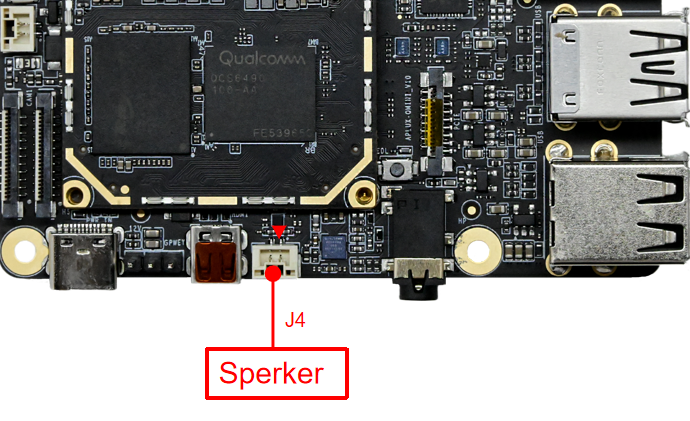
[J4] Speaker interface, 1×2×1.25mm, connector model: WAFER-GH1.25-2PLB, manufacturer: XUNPU. It has an onboard power amplifier with a maximum output of 3.24W×1@4Ω.
PIN Definition:
| Pin# | Definition | Note |
|---|---|---|
| 1 | VO- | Negative BTL audio output |
| 2 | VO+ | Positive BTL audio output |
WiFi/BT Antenna Interfaces
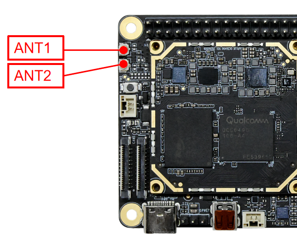
[ANT1, ANT2] Antenna interfaces for the onboard FCU760K wireless module (iPEX Gen 1). The module supports Wi-Fi 6 and Bluetooth 5.4. Antennas and coaxial pigtails must match the onboard RF connectors and be connected according to the corresponding RF port definitions.
SW1 Flashing Mode Button
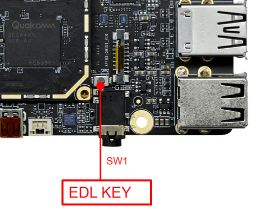
[SW1] SMD flashing button. Press and hold it, then power on for about 3 seconds and release to enter flashing mode.
SW2 Power Button
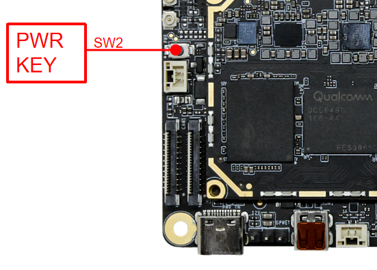
[SW2] Power-on button.
LED
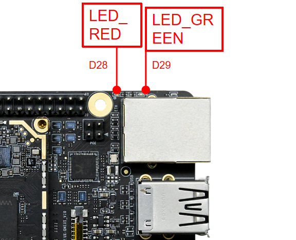
The board has one red LED and one green LED. During normal boot the green LED stays on, and the red LED lights up when the system is abnormal.
Precautions
Please note the following key points when assembling and using the carrier board:
- Relative humidity: 0~95% non-condensing.
- Operating temperature reference range: -20°C ~ 50°C; the whole device should complete thermal design and functional validation under the target environment and full business load.
- Storage temperature: -45°C ~ 80°C.
- ESD protection is required during assembly and transportation.
- Cables connected to the board's interfaces must not be too long, otherwise signal quality may be affected.
- Do not twist or apply heavy pressure to the board during assembly to avoid deformation.
- Never allow a short circuit between the bare board and other peripherals.
- When connecting external GPIO, UART, I2C or SPI devices, match the signal I/O levels and drive capability. When powering peripherals from interface power pins, observe the current limits specified in each interface section, and verify the combined load on the same power rail and the overall power budget. The speaker must be connected across VO+ and VO-; neither end of the BTL output may be connected to system ground.
Document Information
- Document name: Rhino A1 Mini Development Board Product Specification
- Product name: Rhino A1 Mini
- Product code: A6490PZ2-YSQM01
- Version: V1.2
- Revision date: 2026-10-16
- Scope: The development board and whole-device integration projects based on this hardware platform