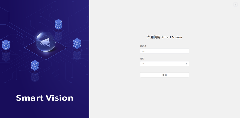
SVE (SmartVision Engine)
SVE (SmartVision Engine) is a camera management box foundational service platform that includes an application development framework for intelligent vision computing terminal devices, intelligent vision terminal device configuration management, application runtime services, and lifecycle management functions. AidLux is an innovative integrated operating system built on ARM hardware, bridging Android/HarmonyOS and Linux system environments. SmartVision runs on the AidLux system, leveraging the AI application runtime underlying SDK support provided by the AidLux platform, aiming to achieve defect detection on target objects and delivering a comprehensive defect detection solution for users.
System Configuration
Network
Network Configuration
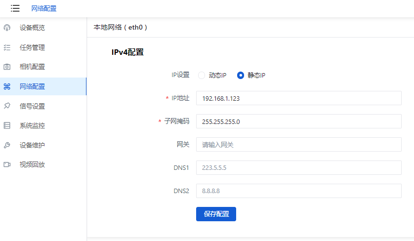
The network configuration page is used to configure the IPv4 address of the camera's wired network port (eth0). The default is a static IP address (192.168.1.123/24).
Display
To be added.
Storage
Device Maintenance
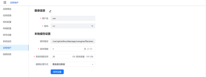
The device maintenance page is mainly for configuring device login information and local cache settings. Here you can modify the SVE software login username and password, as well as configure the local cache retention period, system reserved space, and over-limit processing methods. System reserved space is the threshold at which, when remaining system space reaches the set value, the system reports an alarm and processes according to the configured over-limit handling method.
Video Playback
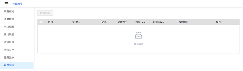
The video playback page mainly stores video file information recorded in "Camera Configuration." You can manage deletions by selecting and clicking batch delete.
Common Tools
Device Overview
💡Tip
SVE Page or Browser Closure Limitation: Closing the SVE page or browser may cause the camera status in the Device Overview to be inconsistent with the actual status.
For example: if cam0 is opened in Camera Configuration, the Device Overview shows cam0's status as Open. After closing and reopening the browser, even though the camera has not been opened elsewhere, the Device Overview still shows the camera status as Open.
The Device Overview mainly introduces camera-related parameter information, such as SoC model, MAC address, IP address, OS information, camera information, camera status, running tasks, etc.
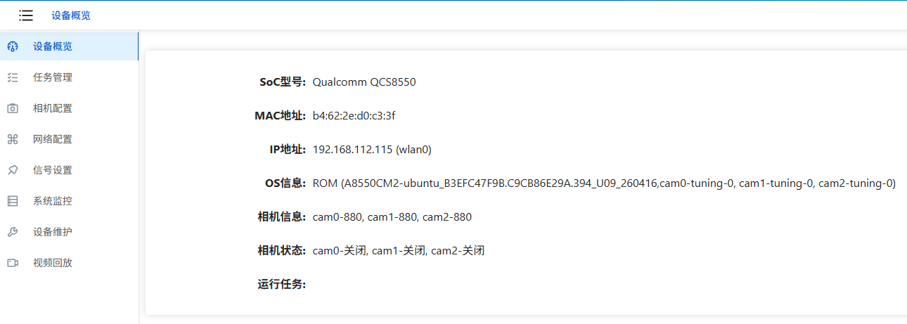
- Device Overview — Main Parameters
| Parameter | Description |
|---|---|
| SoC Model | Displays the camera's chip model |
| MAC Address | Displays the MAC address of the camera's network ports. Shows both wired (eth0) and wireless (wlan0) if both are connected |
| IP Address | Displays the IP address of the camera's network ports. Shows both wired (eth0) and wireless (wlan0) if both are connected |
| OS Information | Displays the ROM version flashed on the camera and the tuning mode used by each camera |
| Camera Information | Displays the models of the main camera and sub-camera lenses |
| Camera Status | Displays the running status of the main camera and sub-cameras |
| Running Tasks | Displays the tasks currently running on the camera |
Task Management
The Task Management page mainly displays the camera's existing AI application list. By default, "Segmentation" and "Image Capture" examples are installed. Users can also add other applications as needed. On this page, you can manage all applications: preview, start/stop, configure, view logs, delete, etc.
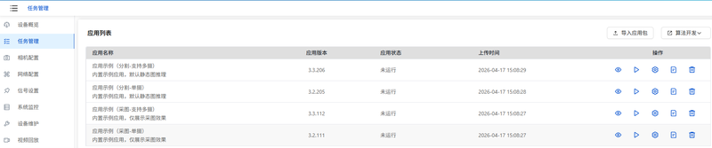
- Task Management — Main Features
| Feature | Sub-Feature | Description |
|---|---|---|
| Import App Package | NA | Import AI offline application package |
| Algorithm Development | Go to AIC Page | After configuration, click to jump to the AIC login interface |
| Set AIC Address | Configure the AIC server login address |
Run and Preview Built-in Applications
💡Tip
Multi-Terminal Imaging Preview Limitation: Running different cameras simultaneously across multiple terminals is not supported.
For example: Browser terminal 1 previews cam0, browser terminal 2 previews cam1, browser terminal 3 previews cam2.
By default, "Segmentation" and "Image Capture" examples are installed in the application list. Take the "Segmentation" app as an example to run and preview inference results.
- Click the Start/Stop App button in the list to run the example application.

Click the Preview button to view the running effect.
After returning to the "Application List" page, click the Enter Imaging Settings button to configure algorithm settings and result processing settings.
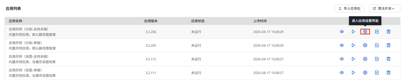
💡Note
Before making these settings, you need to stop the running task to save changes.
Algorithm Settings
This page displays threshold-related parameters for the corresponding AI application. Different applications involve different threshold parameters, supporting dynamic display.
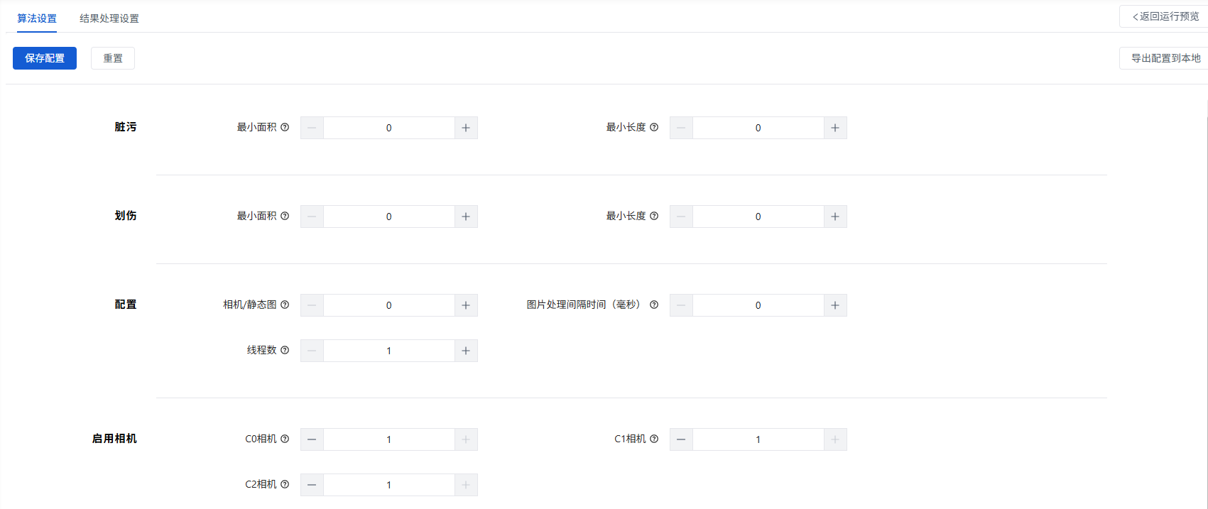
- Algorithm Settings — Feature Description
| Feature | Description |
|---|---|
| Save Configuration | Save the configured algorithm parameters |
| Reset | Restore algorithm parameters to default values |
| Export Configuration to Local | Export the configured algorithm parameters to a local settings.json file |
- Algorithm Settings — Parameter Description
| Parameter | Sub-Parameter | Description |
|---|---|---|
| Contamination | Minimum Area | Minimum area for Segment_0 contamination detection |
| Minimum Length | Minimum length for Segment_0 contamination detection | |
| Scratch | Minimum Area | Minimum area for Segment_0 scratch detection |
| Minimum Length | Minimum length for Segment_0 scratch detection | |
| Configuration | Camera / Static Image | Whether to enable camera; 0-disable, 1-enable |
| Image Processing Interval (ms) | Image processing interval; unit: milliseconds | |
| Thread Count | Number of threads used per camera | |
| Enable Camera | C0 Camera | Enable C0 camera; 0: disable, 1: enable |
| C1 Camera | Enable C1 camera; 0: disable, 1: enable | |
| C2 Camera | Enable C2 camera; 0: disable, 1: enable |
Result Processing Settings
In the result processing settings, there are two items: "Output Signal Settings" and "Data Integration Settings."
Data integration settings allow images captured during detection to be integrated and backed up to other servers. Image types can be selected from original images, result images, and Mask images.
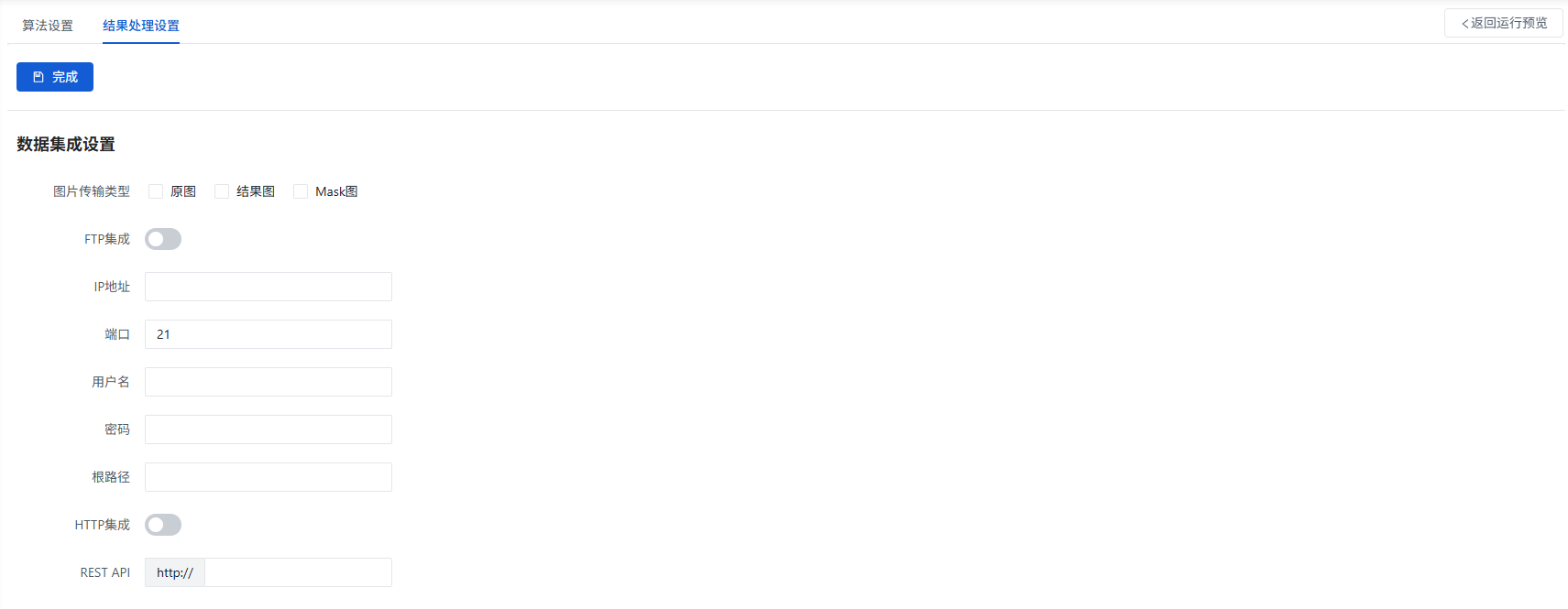
- Result Processing Settings — Feature Description
| Feature | Sub-Feature | Description |
|---|---|---|
| Image Transfer Type | NA | Options: Original Image, Result Image, Mask Image. Can select multiple or single. |
| FTP Integration | IP Address | Enter the FTP server IP address (must be on the same network segment as the camera) |
| Port | FTP server port number, default: 21 | |
| Username | FTP server login username | |
| Password | FTP server login password | |
| Root Path | FTP server path | |
| HTTP Integration | REST API | HTTP server URL address |
Camera Configuration
💡Tip
When accessing SVE via a local browser, different display settings (e.g., 1080p screen + 150% scaling) may cause SVE page layout issues. Set the correct scaling ratio for different displays.
The Camera Configuration page allows you to adjust basic parameters for each lens, such as trigger mode, output channel, resolution, trigger frame rate, exposure mode, white balance, saturation, contrast, sharpness, etc. Use these parameters to optimize imaging results and improve recognition accuracy.
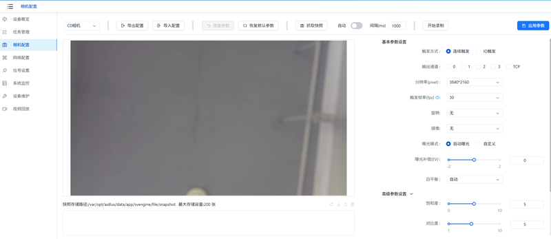
In Camera Configuration, you can not only directly set current camera parameters but also support importing/exporting parameter configurations for batch configuration.
- Camera Configuration — Feature Description
| Feature | Description |
|---|---|
| Camera Selection | Select from connected cameras (Main C0 / Sub C1 / Sub C2) for parameter configuration |
| Export Configuration | Export the corresponding camera's parameter configuration as a JSON file |
| Import Configuration | Import a saved camera parameter configuration |
| Restore Parameters | Restore the last applied parameters |
| Restore Default Parameters | Restore modified parameters to default values |
| Capture Snapshot | Take a photo and save to the default path |
| Auto | When enabled, automatically takes photos at the set interval and saves to the default path |
| Interval (1000ms) | Auto-capture interval, default: 1000ms |
| Start/Stop Recording | Start recording the camera's video; estimated recordable duration is predicted based on available storage space |
Camera parameter settings allow configuration of basic parameters for the currently selected camera. Click Apply Parameters at the top right to take effect.
- Camera Basic Parameter Settings — Description
| Feature | Description |
|---|---|
| Trigger Mode | Options: Continuous Trigger and IO Trigger. Continuous Trigger captures images at the set frequency; IO Trigger captures based on IO signals |
| Output Channel | After configuration, outputs defect detection signals (e.g., high-level signal) through the set channel |
| Resolution | Set the current camera resolution; default varies by camera |
| Trigger Frame Rate (fps) | Configurable only when trigger mode is Continuous Trigger; the frame rate for continuous triggering |
| Rotation | Rotation angle for captured images; default: None |
| Mirror | Mirror mode for captured images; default: None |
| Exposure Mode | Options: Auto Exposure and Custom. Further exposure parameters can be set depending on the selected mode |
| Exposure Compensation (EV) | Fine-tune brightness to make photos brighter or darker. Configurable when Exposure Mode is Auto Exposure |
| Exposure Time (µs) | Controls the duration of light intake. Configurable when Exposure Mode is Custom |
| ISO | Core parameter for overall image brightness. Configurable when Exposure Mode is Custom |
| White Balance | Core setting for controlling image color temperature. Default: Auto |
- Camera Advanced Parameter Settings — Description
| Feature | Description |
|---|---|
| Saturation | Key parameter controlling color intensity |
| Contrast | Key parameter controlling the difference between light and dark areas |
| Sharpness | Key parameter controlling image edge clarity |
- Camera Advanced Parameters — Description
| Feature | Description |
|---|---|
| Saturation | Key parameter controlling color intensity |
| Contrast | The brightness ratio between light and dark areas |
| Sharpness | Metric measuring image edge sharpness |
| Custom White Balance | Disabled by default; when enabled, other parameters can be set |
| Color Setting Mode | Can be set to Professional Mode (default) or Color Temperature Mode |
| R Gain | Adjusts the red component in white balance; configurable in Professional Mode |
| G Gain | Adjusts the green component in white balance; configurable in Professional Mode |
| B Gain | Adjusts the blue component in white balance; configurable in Professional Mode |
| Color Correction Matrix (CCM) | Uses a standard color card as reference to verify color correction effectiveness. Double-click to enter color correction mode. Configurable in Professional Mode |
| Color Temperature (CCT) | Physical measure of light warmth/coolness; configurable in Color Temperature Mode |
| Custom Gamma | Disabled by default; when enabled, Gamma curve can be edited |
CCM Calibration
After enabling custom white balance and setting the color mode to Professional Mode, double-click the Color Correction Matrix setting item to calibrate.
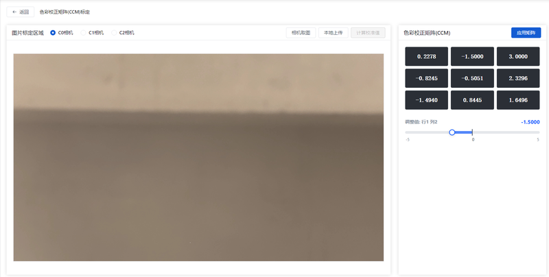
Calibration steps:
Camera Selection Select a connected camera (C0/C1/C2) for calibration. Only one camera can be calibrated at a time.
Image Selection Choose either Camera Capture or Image Upload to upload the color card image. After uploading, if the color card area is not ideal, you can mark the correct range by drawing a box on the image with the mouse.
Calculate Calibration Values After selecting the image and drawing the box, click
Calculate Calibration Valuesto calibrate.Matrix Value Fine-Tuning After calculation, if some values are not ideal, you can fine-tune by clicking the matrix values on the right.
Apply Matrix Once all matrix values are confirmed, click
Apply Matrixto apply to the specific camera.
Edit Gamma Curve
After enabling the custom Gamma curve function, you can edit the curve.
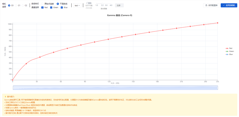
Editing steps:
Camera Selection Select a connected camera (C0/C1/C2) for editing.
Curve Style Selection Curve styles available:
Original CurveandSmooth Curve. Default is 'Smooth Curve'.Channel Selection Channels available:
Red,Green,Blue. All are checked by default. After checking, specific lines can be adjusted.Gamma Value After enabling the Gamma value option, the specific value can be adjusted by sliding.
Save Configuration Profile After adjusting all parameters, click
Save Configuration Profile, enter a name, and save. After switching cameras, previously saved profiles can still be used.Apply to Camera After adjusting all parameters, click
Apply to Camerato apply the current adjustments. After switching cameras, you can also select a specific saved profile and clickApply to Camerato apply it.
Signal Settings
The Signal Settings page is mainly for configuring camera input and output signals. Currently, the camera supports three input signal channels and four output signal channels, meeting the signal I/O requirements of most industrial inspection scenarios.
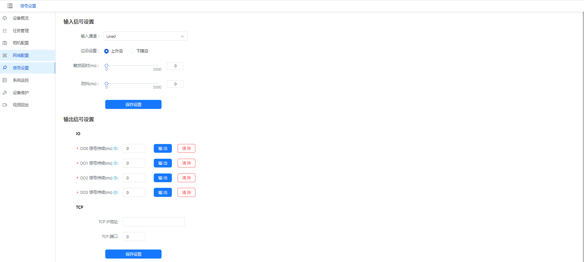
- Input Signal Settings — Parameter Description
| Feature | Sub-Feature | Description |
|---|---|---|
| Input Signal Settings | Input Channel | Signal input channel; options: Line0, Line1, Line2 |
| Edge Setting | Signal input edge setting; options: Rising Edge, Falling Edge | |
| Trigger Delay (ms) | Delay trigger time after signal arrives | |
| Debounce (ms) | Filter out extra signals within the set period |
- Output Signal Settings — Parameter Description
| Feature | Sub-Feature | Description |
|---|---|---|
| Output Signal Settings | IO | Duration of signal output; non-zero means continuous output for the set time, 0 means infinite continuous output |
| TCP | Set TCP IP address and TCP port; click Save Settings button to save | |
| IO Debug | Click IO Debug to navigate to the IO Signal Debug page |
IO Signal Debugging
Click the IO Signal Debug button to enter the IO Signal Debug interface. On this page, you can simulate signal input and output to facilitate debugging the entire inspection workflow without connecting to the actual device signal source during the debugging phase.
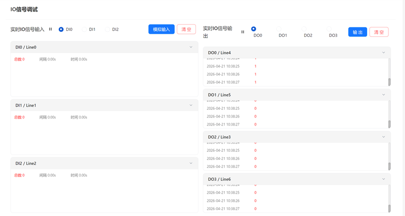
- IO Signal Debug — Parameter Description
| Feature | Description |
|---|---|
| Real-time IO Signal Input | Manually simulate IO signal input based on the selected channel (DI0/DI1/DI2); after simulation, the corresponding channel panel shows the input record. Click the Clear button to clear the latest IO input signal record. |
| Real-time IO Signal Output | Manually simulate IO signal output based on the selected channel (DI0/DI1/DI2); after simulation, the corresponding channel panel shows the output record. Click the Clear button to clear the latest IO output signal record. |
System Monitoring
System Monitoring consists of two pages: "Alarm Information" and "Resource Monitoring".
Alarm Information
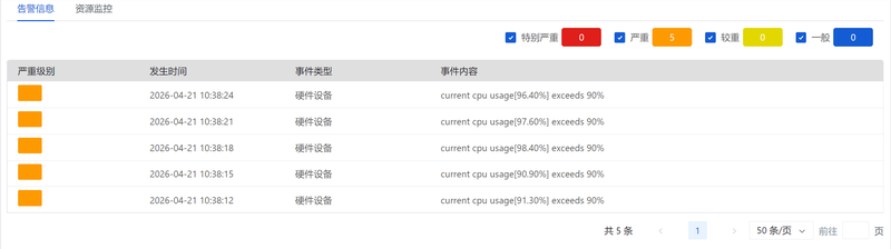
The Alarm Information page primarily records SVE alarm messages. Alarms are classified into five levels: "Critical", "Severe", "Major", "Minor", and "General", with different levels distinguished by different color markers. Each alarm records detailed information including severity level, event timestamp, event type, and event content, helping users quickly and accurately locate issues.
Resource Monitoring
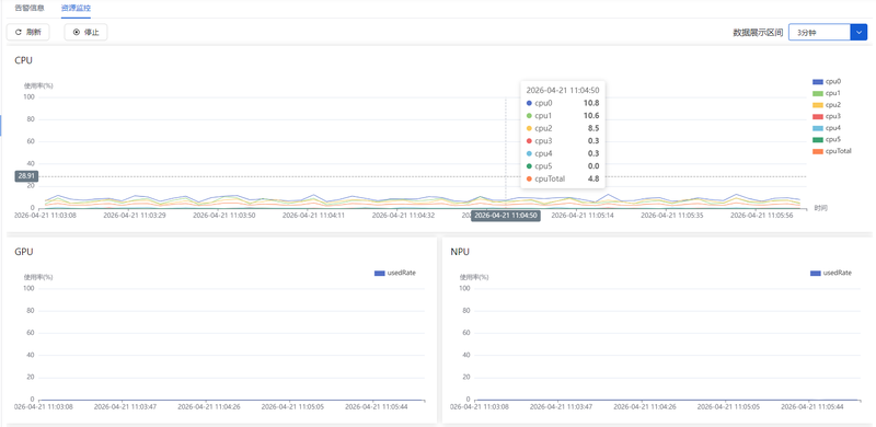
The Resource Monitoring page primarily records device runtime information such as CPU, GPU, NPU, Memory, Storage, and Network (eth0/wlan0), enabling real-time monitoring of device operating status. Monitoring can be controlled via the "Stop/Start" button, and page data display can be adjusted via the "Data Display Interval" option — currently supporting 3-minute and 5-minute data intervals.
Remote Login
SVE Login Methods
Login via Default Port (Recommended)
After the 2nd Generation Smart Camera is powered on, the SVE software starts automatically. You can log in to SVE as follows:
- Connect the device to a wired or wireless network and obtain an IP address
- Open a browser on your local PC and enter: http://[camera IP]:58200/login
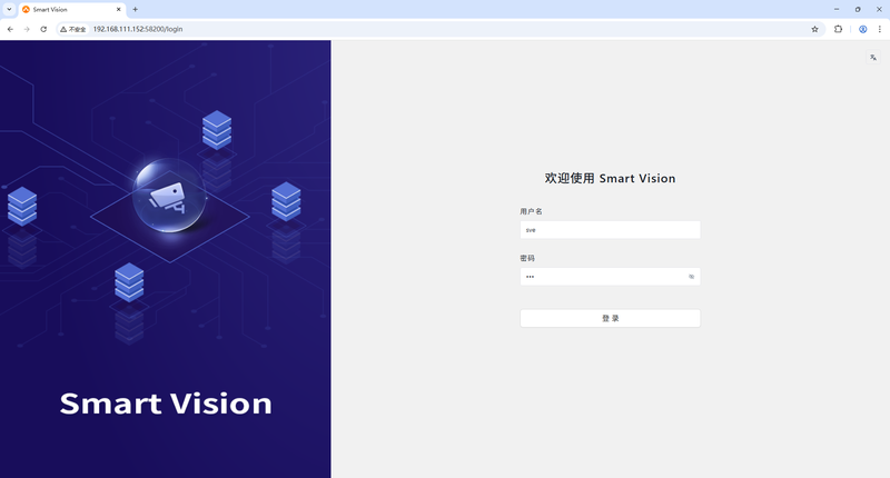
- Enter default username/password: sve/sve
Login via Direct HDMI Connection
The 2nd Generation Smart Camera is equipped with an HDMI interface. You can connect an HDMI display and log in directly to the SVE software:
- Connect the device to an HDMI display and attach a mouse and keyboard via a Type-C hub
- After powering on, the SVE login screen is displayed by default on the HDMI display
Enter the default username/password to log in to SVE: sve/sve